Radiating structure and mounting structure for independent graphics card of computer

A technology of independent graphics card and heat dissipation structure, applied in the direction of electrical digital data processing, digital processing power distribution, instruments, etc., can solve the problems of increasing the size and shape of the radiator, large power supply box, and cumbersome installation, so as to save material costs and reduce Space volume, the effect of increasing the heat dissipation area

Pending Publication Date: 2016-07-27
周奋豪
View PDF7 Cites 14 Cited by
  • Summary
  • Abstract
  • Description
  • Claims
  • Application Information

AI Technical Summary

Problems solved by technology

The following five problems often occur: First, due to the excessive tightening of the screws / expansion pins, the force between the radiator and the motherboard is too large, resulting in different degrees of deformation and bending of the motherboard
Second, sometimes due to the unbalanced stress on the four screws when they are fastened, the surface of the CPU chip and the heat conduction base of the heat sink are partially warped, resulting in a small gap, which greatly increases the distance between the CPU chip and the heat conduction base of the heat sink. Thermal conductivity, which hinders the heat transfer from the CPU chip to the radiator
Thirdly, the traditional CPU radiators and supporting fasteners and parts are various, and the installation is more cumbersome, and most of them take several minutes to more than ten minutes.
Fourth, when some traditional CPU coolers are installed on the motherboard, they cannot be moved or can only move in one direction
As a result, the CPU cooler sometimes conflicts with the position of components on some motherboards, and cannot be installed normally.
Fifth, most traditional high-end CPU radiators can only blindly increase the size and shape of the radiator in order to achieve better cooling effect
If air cooling is adopted, the cold air flowing in from the air inlet is disturbed by the CPU cooling fan on the motherboard and the graphics card cooling fan, and the cold air outside the chassis cannot flow through the independent graphics card radiator in a complete, unidirectional and orderly manner. Efficient heat dissipation, because of the unscientific and tight air duct in the chassis, the cold air flowing into the independent graphics card and CPU radiator is entrained with reflowing hot air, which affects the heat exchange effect of the radiator
[0012] Fourth, the independent graphics card radiator is placed horizontally and parallel, which is very unfavorable for the natural upward lift of air heat flow
[0014] 4) Cooling air duct: The design of the cooling air duct in the traditional desktop mainframe is unscientific and disorderly, and there is almost the phenomenon of backflow hot air
The former, no matter how high or low the temperature inside the chassis, always has the same speed, which is unscientific; the latter, the fan must first have the PWM function, and then it needs to be turned on and set under the motherboard BISS, and the user needs to have certain professional knowledge
Moreover, there are many types of fans. If the fans in PWM speed control mode are too noisy or the wind speed is too low, users have almost no way to effectively adjust them.
[0016] 5) Power supply: The power supply box in the traditional desktop mainframe box is relatively large in size. Its function is to directly convert the input municipal AC power into DC output with different voltage values ​​required by each hardware, and use many RVV wires to connect with each hardware respectively. The design and layout of the traditional main box is backward, resulting in dense and criss-crossing of various wires in the main box, which greatly occupies and wastes the space volume in the main box and affects the beauty of the main box, and also hinders the convenience of users.

Method used


Image

  • Radiating structure and mounting structure for independent graphics card of computer
  • Radiating structure and mounting structure for independent graphics card of computer
  • Radiating structure and mounting structure for independent graphics card of computer

Examples


Embodiment Construction

[0066] The present invention will be further described below in conjunction with accompanying drawing:

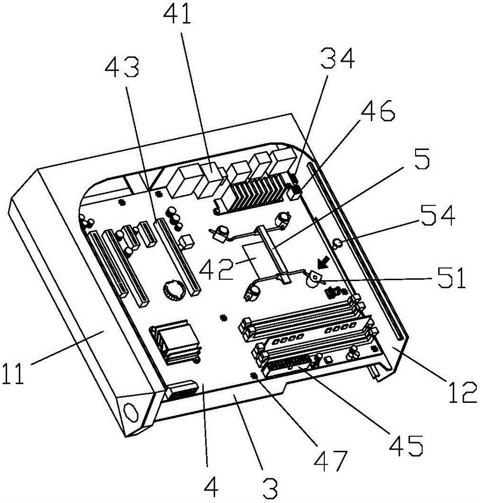
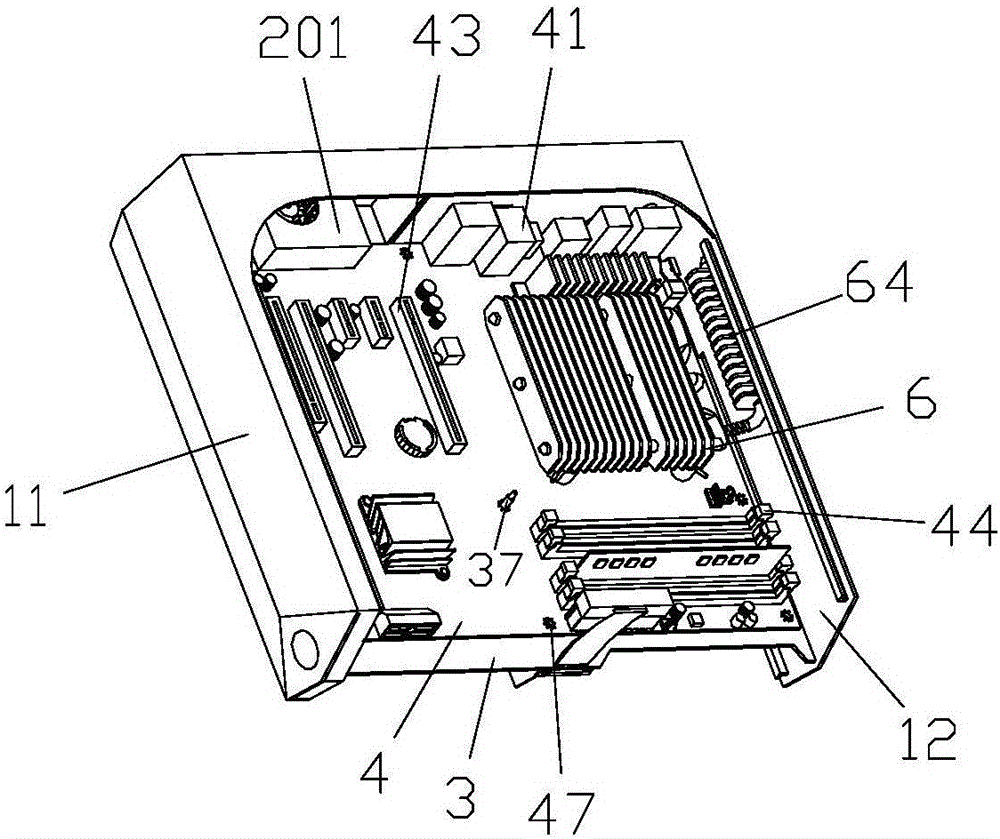
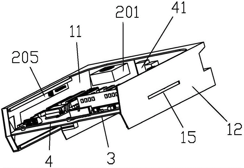
[0067] Such as Figure 1-Figure 14 , a kind of computer case, comprises computer host shell 1 / skeleton and computer hardware, and wherein computer hardware comprises main board 4, hard disk 203 / power supply box 9 and corresponding radiator, is provided with dividing plate 3 in the computer host shell 1 / skeleton, separates The board 3 divides the cavity formed by the computer host shell 1 / skeleton into two, and the main board 4 is fixed on one side of the partition 3 , which is the front of the partition 3 . The hard disk 203 / power box 9 is arranged on the other side of the partition 3 , which is the back side of the partition 3 . Mainboard 4, hard disk 203 / power supply box 9 are all parallel to the side of partition 3, described partition 3 front or / and back or partition 3 are provided with circuit, and partition 3 is provided with for computer hardware and carries out ci...


PUM


Abstract

The invention discloses a radiating structure for an independent graphics card of a computer. The radiating structure comprises a mounting structure for the independent graphics card and a radiator. The radiator which is flat integrally is matched with the independent graphics card and is provided with a front surface and a back surface, a heat conduction base is arranged on the front surface of the integrally flat radiator, a main body of the radiator comprises radiating fins, and the radiating fins are parallelly arrayed at intervals. An outward smooth surface of the heat conduction base flatly clings to a GPU (graphics processing unit) chip of the independent graphics card, the back surface of the radiator is in contact with a partition plate surface in a host case of the computer in a parallelly clinging manner, a space of a host of the computer is halved by a partition plate, computer hardware including a mainboard, hard disks, power boxes and a fan are parallelly mounted on a surface or two surfaces of the partition plate or are mounted on the single surface or the two surfaces of the partition plate in a parallelly clinging contact manner, and the independent graphics card is parallel to the partition plate. The invention further discloses the mounting fixing structure for the independent graphics card of the computer. The radiating structure and the mounting fixing structure have the advantages that various independent graphics cards can be compatibly arranged in the ultrathin case, the effective radiating area of the independent graphics card can be enlarged, and the radiating efficiency of the independent graphics card can be enhanced.

Description

technical field [0001] The invention relates to the technical field of computer hardware equipment, in particular to a technology for the installation and heat dissipation structure of a computer independent graphics card. Background technique [0002] The mainstream of existing traditional desktop mainframes is a tower-type mainframe, and its overall body shape is a cuboid. The main chassis of desktop computers can be divided into horizontal type and vertical type, and vertical type is generally the most common. All physical components in the main chassis are generally called computer hardware, including motherboards, hard drives, CPUs, memory sticks, discrete graphics cards, optical drives, power supplies, and radiators. The existing tower-type main chassis is a non-ultra-thin chassis, which is large in size and heavy in weight. [0003] 1) Hardware layout and routing: At present, the hardware layout design in the traditional desktop mainframe box is that almost only o...

Claims


Application Information

Patent Timeline
Patent Type & Authority Applications(China)
IPC IPC(8): G06F1/18G06F1/20
CPCG06F1/183G06F1/20G06F1/18
Inventor 周奋豪
Owner 周奋豪
Why Eureka
Try Eureka