
Test fixture

A test fixture and test pin technology, which is used in semiconductor/solid-state device testing/measurement, electrical components, semiconductor/solid-state device manufacturing, etc., and can solve the problems of poor safety performance, complex structure, and inconvenient use of test fixtures. , to achieve the effect of improving equipment safety, simple structure and convenient operation

Pending Publication Date: 2016-07-27
刘友富
View PDF5 Cites 0 Cited by
  • Summary
  • Abstract
  • Description
  • Claims
  • Application Information

AI Technical Summary

Problems solved by technology

[0002] The word "fixture" is directly translated from Japanese Chinese characters. It is an appliance used to assist operations. Common fixtures include: automation equipment, tooling fixtures, test fixtures, SMT furnace fixtures, Precision parts, blades, DVD read heads, etc., are simply a kind of auxiliary production equipment on the production line. Test fixtures refer to instruments used for testing. There are many types of test instruments, and they have different structures according to different test requirements. Features, when conducting voltage penetration tests on insulators such as LED copper substrates or aluminum substrates, the assistance of test fixtures is required. In the prior art, the test fixtures are used for voltage penetration of insulators such as LED copper substrates or aluminum substrates. When in use, the structure is relatively complicated, and the use is not convenient enough. Because a high voltage is often generated during the test process, the safety performance of the traditional test fixture is not good. Aiming at the above problems, the present invention is specially designed to solve it.

Method used


Image

  • Test fixture
  • Test fixture
  • Test fixture

Examples


Embodiment Construction

[0016] The technical solution of this patent will be further described in detail below in conjunction with specific embodiments.

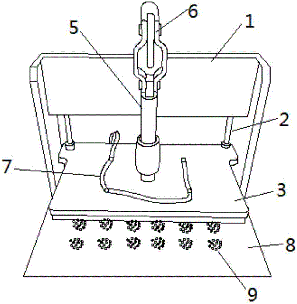
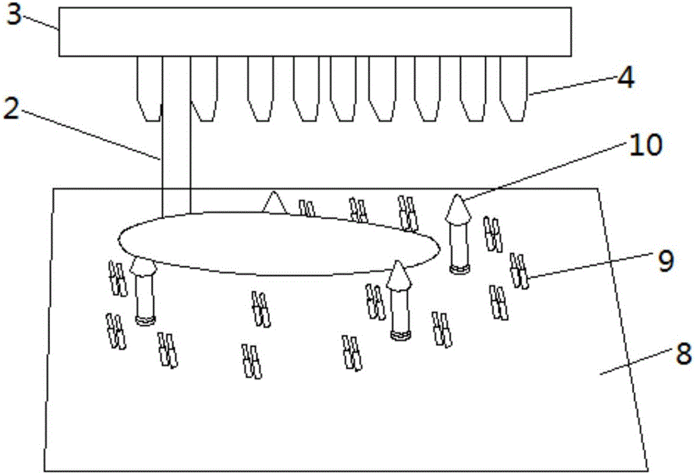
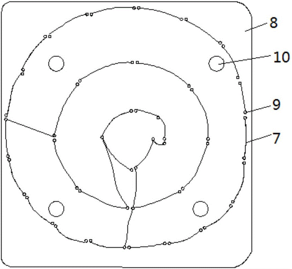
[0017] A test fixture, comprising a fixed frame 1, the two sides of the fixed frame 1 are connected to the lower pressure plate 3 through iron rods 2, the lower pressure plate 3 is made of insulating material, the lower part of the lower pressure plate 3 is provided with a plurality of lower pressure columns 4, and the middle part of the lower pressure plate 3 There is a lid-closing pressure rod 5, and the upper part of the lid-closing pressure rod 5 is provided with a quick clamping hand 6, which is used to adjust the height of the lower pressing plate 3. The upper part of the quick clamping hand 6 is provided with a pressure handle, and the lower pressing plate 3 is provided with a The high-voltage connection line 7 is provided with a high-voltage input terminal at the end of the high-voltage connection line 7. The lower part of the lower pressure...


PUM


Abstract

The invention discloses a test fixture, comprising a fixed frame, wherein two sides of the fixed frame are connected with a lower pressure plate via guide rods, a plurality of lower pressure columns are arranged at the bottom the lower pressure plate, a cover closing pressure lever is arranged in the middle of the lower pressure plate, a quick clamp is arranged at the upper part of the cover closing pressure lever, a pressure handle is arranged at the upper part of the quick clamp, a high-voltage connecting wire is arranged on the lower pressure plate, a high-voltage input end is arranged at the end of the high-voltage connecting wire, a test plate is arranged below the lower pressure plate, a plurality of test pin groups are uniformly arranged on the test plate, the test pin groups are all connected with the high-voltage connecting wire, a safety alarm device for cutting off power is connected to the high-voltage connecting wire, a plurality of bearing columns are arranged on the test plate, and a spring is arranged in each bearing column. Compared with the prior art, the test fixture has the advantages of simple structure, convenience in operation and strong practicability, and can be used for effectively testing the voltage penetrability of insulators such as LED (Light Emitting Diode) copper substrates or metal substrates and the like; and by adopting the safety alarm device, the safety of equipment can be greatly improved, the text fixture is safe in use, the test result is accurate, and the test performance is reliable.

Description

technical field [0001] The invention relates to the technical field of mechanical equipment, in particular to a test fixture. Background technique [0002] The word "fixture" is directly translated from Japanese Chinese characters. It is an appliance used to assist operations. Common fixtures include: automation equipment, tooling fixtures, test fixtures, SMT furnace fixtures, Precision parts, blades, DVD read heads, etc., are simply a kind of auxiliary production equipment on the production line. Test fixtures refer to instruments used for testing. There are many types of test instruments, and they have different structures according to different test requirements. Features, when conducting voltage penetration tests on insulators such as LED copper substrates or aluminum substrates, the assistance of test fixtures is required. In the prior art, the test fixtures are used for voltage penetration of insulators such as LED copper substrates or aluminum substrates. When in use...

Claims


Application Information

Patent Timeline
IPC IPC(8): H01L21/66H01L21/67
CPCH01L21/67253H01L22/14
Inventor 刘友富
Owner 刘友富
Learn More