Laser-assisted frit encapsulation apparatus and method

A laser-assisted and packaging device technology, which is applied in the manufacture of electrical components, electrical solid devices, semiconductor/solid devices, etc., can solve the problems of reducing packaging quality, rising packaging temperature, and aggravating thermal stress, so as to reduce the difficulty of control and implementation, Avoiding the reduction of yield and better packaging effect

Active Publication Date: 2018-07-20
SHANGHAI MICRO ELECTRONICS EQUIP (GRP) CO LTD
View PDF8 Cites 0 Cited by
  • Summary
  • Abstract
  • Description
  • Claims
  • Application Information

AI Technical Summary

Problems solved by technology

However, the laser power cannot be increased too much. This is because when the laser power is too high, it will cause a series of problems. First, the package temperature will rise significantly, which will affect the performance of the OLED device, and the same laser power is different for different The thickness of the glass frit has a difference in thermal effect, which leads to the intensification of thermal stress, causing problems such as cracks and warping, and reduces the packaging quality
[0005] In addition, the current OLED laser packaging mainly uses the circumferential scanning method, and its scanning rate is relatively low. The general scanning rate is 20mm / s, and its production rate is low. However, the scanning rate of the quasi-synchronous scanning method can reach 3m / s, and the production rate is relatively low. It can be greatly improved in terms of the circumferential scanning method
However, the pyrometer itself has a sampling frequency limitation, so it can only be used in the low-speed circular scanning method, but not in the quasi-synchronous scanning method with higher productivity and faster movement speed

Method used


Image

  • Laser-assisted frit encapsulation apparatus and method
  • Laser-assisted frit encapsulation apparatus and method
  • Laser-assisted frit encapsulation apparatus and method

Examples


Embodiment 1

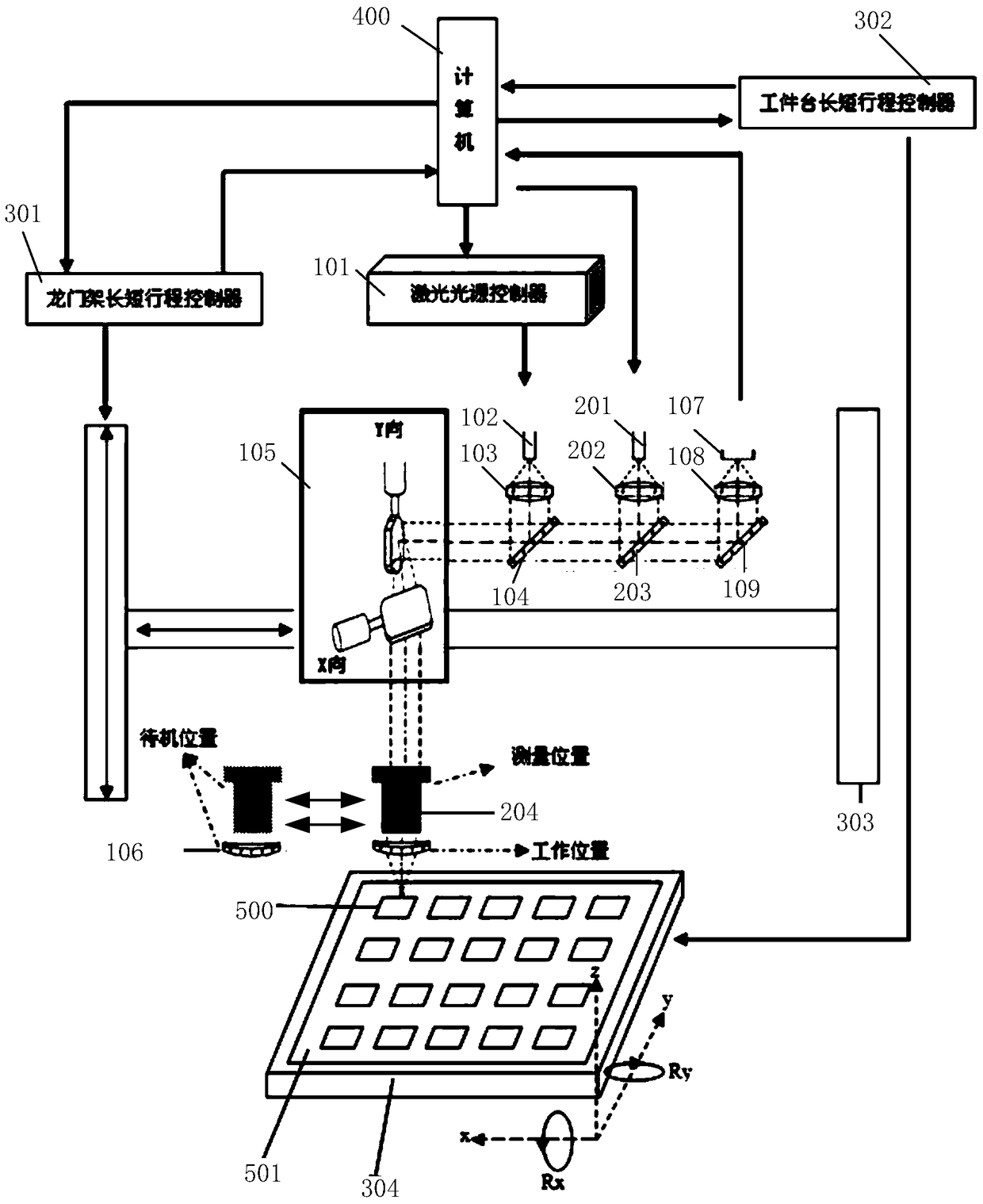
[0058] This embodiment considers the scene with higher packaging quality requirements, and uses the principle of Michelson interferometry to obtain relevant film thickness information, that is, this embodiment adjusts the vertical position and angle of the glass frit 500, so that the image detector 107 collects Interference fringes, based on the principle of light wave superposition, produce alternating bright and dark fringes in the interference field. According to the difference of interference fringes reflected from the glass frit 500, the frit 500 film of the measured point is obtained by analyzing and processing the interference fringes through the host module 400 thick information.

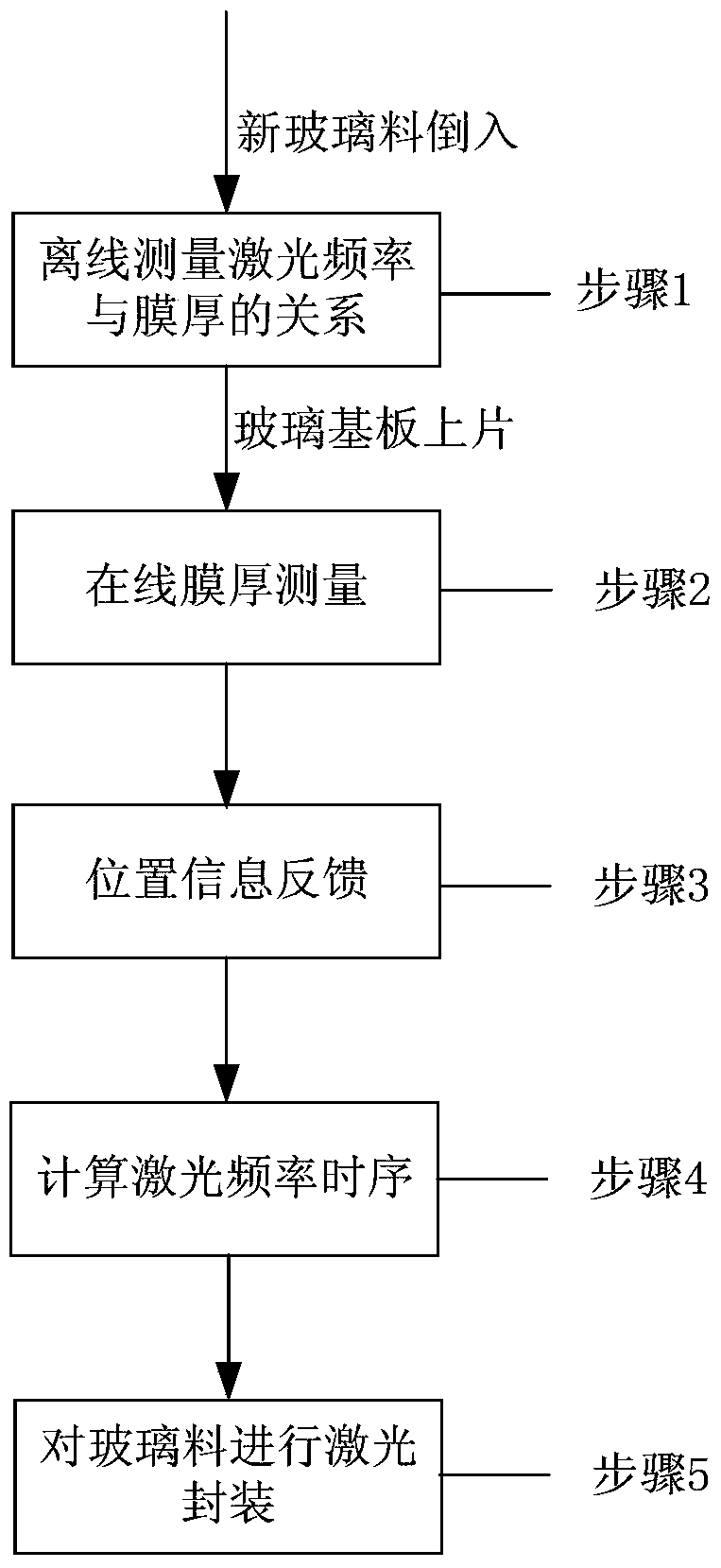
[0059] For details, please refer to figure 2 , and combined with figure 1 , the laser-assisted frit encapsulation method will be described in detail below, including the following steps:

[0060] Step 1: Measure the relationship between the film thickness of the new glass frit 500 and the...

Embodiment 2

[0072] This embodiment considers the production rate optimization scenario, so the film thickness value of the glass frit 500 is synchronously measured by the triangulation method when performing field-by-field leveling and focusing, so as to avoid the reduction of the overall production rate.

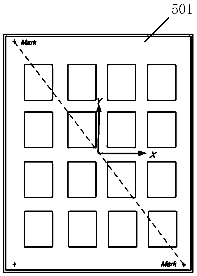
[0073] The center of the triangulation method is: because the reflectivity of the glass frit 500 itself is very low, the reflection signal cannot be collected effectively, so the height of the cavity on both sides of the glass frit is measured here, and the average value of the height of the left and right cavities is calculated. The height of the glass frit 500 is calculated.

[0074] Such as Figure 6 As shown, the light source emits incident light, which is reflected by the lower surface of the upper glass substrate 501 and the upper surface of the lower glass substrate 501, so that the CCD can obtain two beams of reflected parallel light signals, through the formula H ccd =2γ·Z·si...


PUM


Abstract

The invention discloses a laser-assisted frit packaging device and method, and the device comprises a laser scanning module which is used for the scanning and packaging of frit on a workpiece platform; a film thickness collection module which is used for measuring the thickness of the frit and feeding back the film thickness to a host module; a position information processing module which is used for feeding back the position information of a film thickness measurement point on the frit to the host module; and the host module which is used for calculating the laser power matched with the measurement point according to the detected film thickness of the frit and the corresponding position information, and feeding back the information to the laser scanning module. According to the invention, the device is additionally provided with the film thickness collection module, reduces the implementation difficulty of a film thickness measurement function, and enables the implementation of the synchronous control of the film thickness and the measurement position to be easier because an original optical path is employed.

Description

technical field [0001] The invention relates to the field of integrated circuit manufacturing, in particular to a laser-assisted glass frit packaging device and method. Background technique [0002] In recent years, OLED (Organic Light-Emitting Diode, Organic Light-Emitting Diode) has been widely used due to its excellent characteristics such as self-illumination, simple structure, ultra-thin, fast response, high color contrast, wide viewing angle, low power consumption and flexible display. It has become an important development direction in the field of flat panel display and lighting. [0003] At present, the organic light-emitting materials and electrodes used in OLED displays are extremely sensitive to water vapor and oxygen in the surrounding environment, and due to the interaction, they deteriorate and cause dark spots, which seriously affect their lifespan. For this reason, extremely harsh hermetic encapsulation of OLEDs is required. Laser-assisted glass frit packa...

Claims


Application Information

Patent Timeline
Patent Type & Authority Patents(China)
IPC IPC(8): H01L51/56
Inventor 任书铭陈海华黄元昊
Owner SHANGHAI MICRO ELECTRONICS EQUIP (GRP) CO LTD
Why Eureka
Try Eureka