
DC high-voltage polarity reversal device

A polarity inversion, high-voltage technology, applied in the direction of conversion equipment without intermediate conversion to AC, can solve the problems of distorted local electric field, difficult development of extruded plastic DC cables, low carrier mobility, etc., to achieve DC High withstand voltage, adjustable inversion time and mode, good charge retention effect

Active Publication Date: 2016-07-27
TSINGHUA UNIV +3
View PDF6 Cites 2 Cited by
  • Summary
  • Abstract
  • Description
  • Claims
  • Application Information

AI Technical Summary

Problems solved by technology

[0004] Under the high-voltage DC electric field, the phenomenon of space charge widely exists in solid dielectrics and composite dielectrics, which greatly restricts the development of DC cable transmission technology and the improvement of voltage levels
However, under the actual DC cable operating conditions such as polarity reversal, power on and off, due to the small carrier mobility and other reasons, the same polarity charges become opposite polarity charges after polarity reversal, which seriously distorts the local electric field. Even cause a series of insulation aging damage phenomena such as partial discharge, electric tree aging, breakdown, etc.
[0005] Due to the existence of polarity reversal operating conditions under DC conditions, it is difficult to develop extruded plastic DC cables. Most of the high-voltage DC cable systems controlled by current source converters use non-drip oil-impregnated paper insulated cables.

Method used


Image

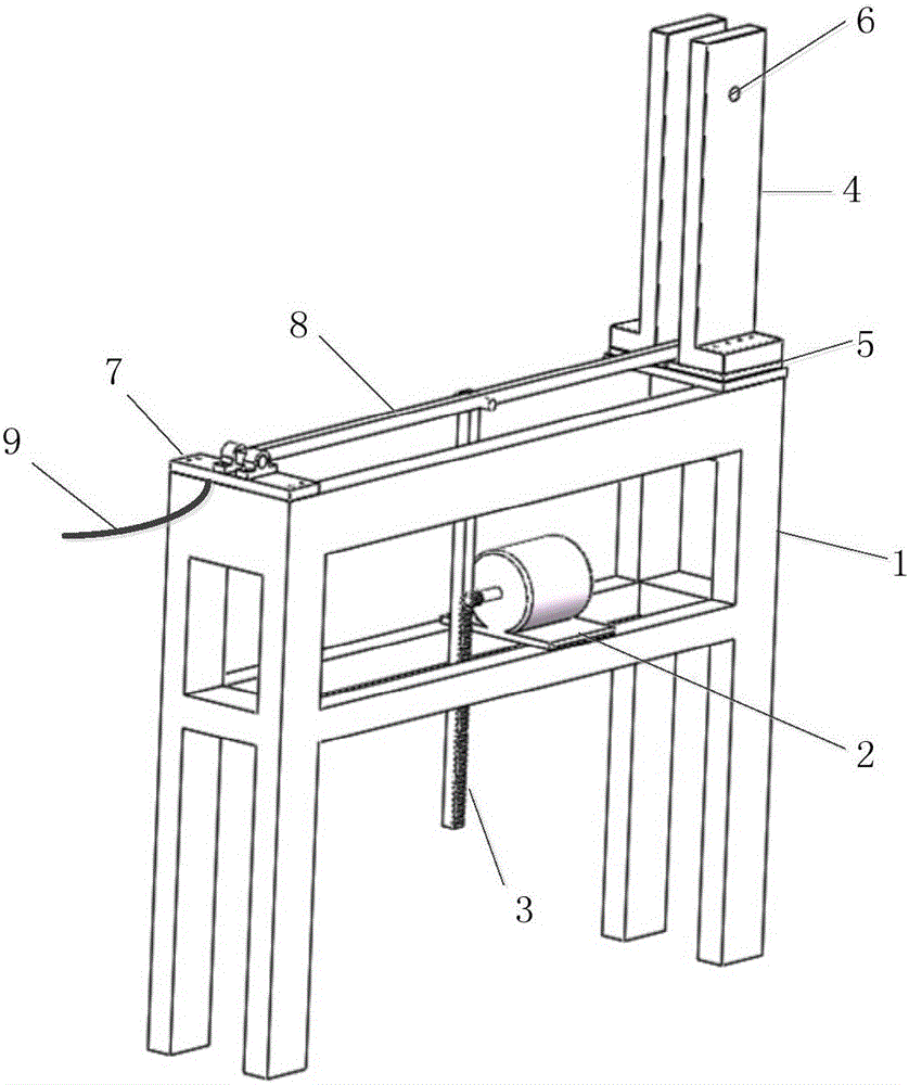
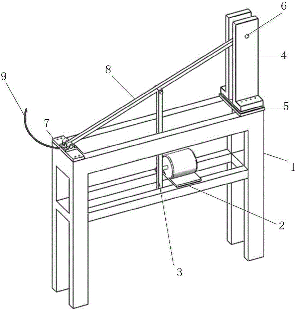
  • DC high-voltage polarity reversal device
  • DC high-voltage polarity reversal device

Examples


Embodiment Construction

[0019] Embodiments of the present invention are described in detail below, examples of which are shown in the drawings, wherein the same or similar reference numerals designate the same or similar elements or elements having the same or similar functions throughout. The embodiments described below by referring to the figures are exemplary only for explaining the present invention and should not be construed as limiting the present invention.

[0020] In describing the present invention, it should be understood that the terms "center", "longitudinal", "transverse", "upper", "lower", "front", "rear", "left", "right", " The orientations or positional relationships indicated by "vertical", "horizontal", "top", "bottom", "inner" and "outer" are based on the orientations or positional relationships shown in the drawings, and are only for the convenience of describing the present invention and Simplified descriptions, rather than indicating or implying that the device or element refe...


PUM


Abstract

The invention discloses a DC voltage polarity reversal device, and the device comprises: a first high-voltage input end which is used for accessing positive polarity high-voltage DC power supply or negative polarity high-voltage DC power, a second high-voltage input end which is used for accessing a high-voltage DC power supply of which polarity is opposite to the first high-voltage input end, a high-voltage output end, a metal guide rod of which one end is jointed with a high-voltage output end and the other end is alternately connected with the first high-voltage input end and the second high-voltage input end, and a driving device which is connected with the metal guide rod through a insulating transmission rod and can drive the connection state of the metal guide rod between the first high-voltage input end and the second high-voltage input end. The device comprises the following advantages of high DC voltage withstand, adjustable reversal time and mode and good electric charge retention effect in switching process.

Description

technical field [0001] The invention relates to the technical field of direct current high voltage, in particular to a direct current high voltage polarity reversal device. Background technique [0002] In recent years, with the rapid growth of my country's power load, EHV and UHV power transmission projects have also ushered in a golden period of rapid development. Since the 1950s, countries such as Sweden and the United States have begun to explore high-voltage direct current transmission technology, and nearly a hundred high-voltage direct current transmission projects have been put into operation so far. DC transmission has the advantages of UHV, long distance, large capacity, and low loss, and is the mainstream direction advocated by the international large power grid. As an important part of HVDC transmission project, DC cable transmission technology provides an effective solution to realize the interconnection between clean energy bases such as wind power and solar e...

Claims


Application Information

Patent Timeline
Patent Type & Authority Applications(China)
IPC IPC(8): H02M3/16
CPCH02M3/16
Inventor 周远翔张灵尹琪张云霄陈明滕陈源王健一孙清华陈铮铮赵健康程子霞
Owner TSINGHUA UNIV
Learn More