
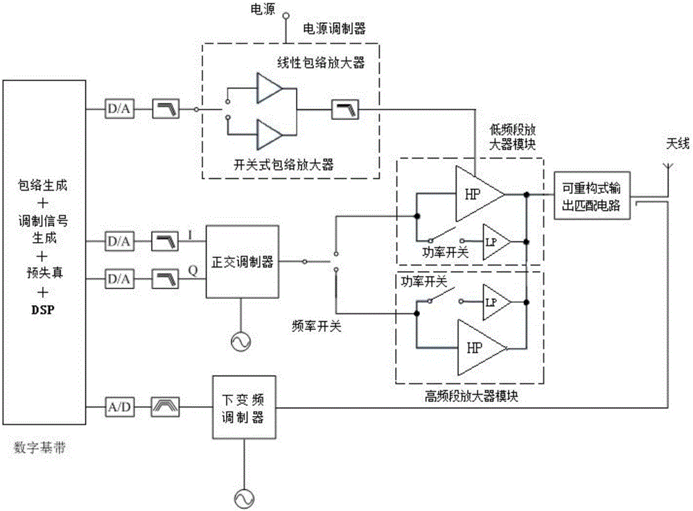
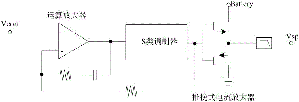
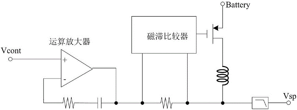
Circuit structure of envelope tracking radio frequency power amplifier

An amplifier circuit and envelope amplifier technology, applied in power amplifiers, high-frequency amplifiers, amplifiers, etc., can solve problems such as bulky volume and complex circuit structure, and achieve the effect of improving overall efficiency, high efficiency, and improving linearity.

Active Publication Date: 2016-07-27
臻智微芯(广州)技术有限公司
View PDF6 Cites 11 Cited by
  • Summary
  • Abstract
  • Description
  • Claims
  • Application Information

AI Technical Summary

Problems solved by technology

In Chinese patent 201510219484.3, an automatically aligned envelope tracking power amplifier structure is proposed, which uses a single-stage envelope modulator, detector and delay circuit, so the circuit structure is relatively complex and bulky
In addition, this structure cannot well realize the compensation and calibration of the feedback signal

Method used


Image

  • Circuit structure of envelope tracking radio frequency power amplifier
  • Circuit structure of envelope tracking radio frequency power amplifier
  • Circuit structure of envelope tracking radio frequency power amplifier

Examples


Embodiment Construction

[0019] A preferred embodiment of the present invention, a multi-frequency multi-mode envelope tracking radio frequency power amplifier circuit structure comprising the envelope tracking radio frequency power amplifier circuit structure, including a power modulator, a low frequency band amplifier module and a high frequency band amplifier A module with a built-in digital baseband of a DSP processor connected to the power modulator, the power modulator connected to the low-frequency amplifier module, and the high-frequency and low-frequency amplifier modules are connected in parallel by low-power and high-power amplifiers All the power amplifiers are connected together to share a reconfigurable output matching network, and the digital baseband also includes a digital predistortion and slow envelope control signal generation circuit. The power modulator includes a linear envelope amplifier and a switch-type envelope amplifier connected in parallel controlled by a switch; when a hi...


PUM


Abstract

The invention discloses a circuit structure of an envelope tracking radio frequency power amplifier. The circuit structure comprises a power supply modulator, a low-frequency-band amplifier module and a high-frequency-band amplifier module, wherein the power supply modulator is connected with the low-frequency-band amplifier module, each of the high-frequency-band amplifier module and the low-frequency-band amplifier module consists of a low-power amplifier and a high-power amplifier which are connected in parallel, and all power amplifiers are connected and share a reconfigurable output matching network. By the adoption of the structure, the high-efficiency, multimode and multi-frequency radio frequency power amplifier suitable is achieved. The circuit structure combines with a digital signal processing technique, a switch switching technique and a reconfigurable technique, and the overall efficiency, linearity and integrity of the power amplifier are improved. The linearity is improved by adopting the signal processing technique for digital pre-distortion calibration and a differential stacking type power amplifier structure, accordingly the high linearity requirement of 3G / 4G is met, and the efficiency is also kept at a higher level.

Description

technical field [0001] The invention relates to an amplifier circuit, in particular to a radio frequency power amplifier circuit. Background technique [0002] RF power amplifier is an indispensable and important part of various wireless communication equipment, which can amplify the weak signal without distortion and radiate it through the antenna. With the development of wireless communication technology, smart mobile phones have been rapidly developed, and need to satisfy the user experience of high-speed data streams for the majority of users. Therefore, most modern mobile communication systems use modulation methods with high spectral efficiency, such as QPSK and OFDM, etc. Typical representatives are 3G and 4G mobile communication technologies, and such signals have a high peak-to-average ratio. Therefore, when RF power amplifiers When working in the power back-off area, the efficiency is low. With the continuous evolution of globalization, in order to meet the needs...

Claims


Application Information

Patent Timeline
Patent Type & Authority Applications(China)
IPC IPC(8): H03F1/32H03F3/189H03F3/20
CPCH03F1/3241H03F3/189H03F3/20
Inventor 林俊明章国豪张志浩余凯
Owner 臻智微芯(广州)技术有限公司
Learn More