
Designing and forming method for anatomical bone plate of individuation bone model

A molding method and technology of bone model, applied in the direction of internal bone synthesis, outer plate, computer-aided planning/modeling, etc., can solve the problem of poor steel plate molding, precision surface color, roughness effect, poor anatomical matching of bone plate, etc. problems, to reduce fracture malunion, increase the risk of fracture, and reduce fatigue strength

Inactive Publication Date: 2016-08-03
SOUTHERN MEDICAL UNIVERSITY
View PDF5 Cites 31 Cited by
  • Summary
  • Abstract
  • Description
  • Claims
  • Application Information

AI Technical Summary

Problems solved by technology

This orthodromic design method can solve some data source problems through physical measurement, but it is often limited by the complexity of the surface structure of orthopedic internal fixation devices and the highly individual differences in the curvature of the bone surface, so the anatomical matching degree of the designed bone plate is poor , it is difficult to exert the best fixation performance; the reverse software modeling based on 3D scanning mainly adopts the method of surface point cloud acquisition, and its accuracy is easily affected by the surface color and roughness of the entity, and it is often necessary to paint the surface of the bone plate under test "Contrast enhancer" or paint treatment, and even then, the reconstructed model is still distorted
Due to individual differences, it is difficult for the existing conventional bone plate to achieve an individualized highly anatomical matching design, resulting in poor shaping of the plate during operation, or the implant cannot fully match the bone anatomy of the affected limb, resulting in delayed fracture healing and malunion in some patients. Or nonunion, or even fracture of the implant, difficulty in taking it out, etc.

Method used


Image

  • Designing and forming method for anatomical bone plate of individuation bone model
  • Designing and forming method for anatomical bone plate of individuation bone model
  • Designing and forming method for anatomical bone plate of individuation bone model

Examples


Embodiment Construction

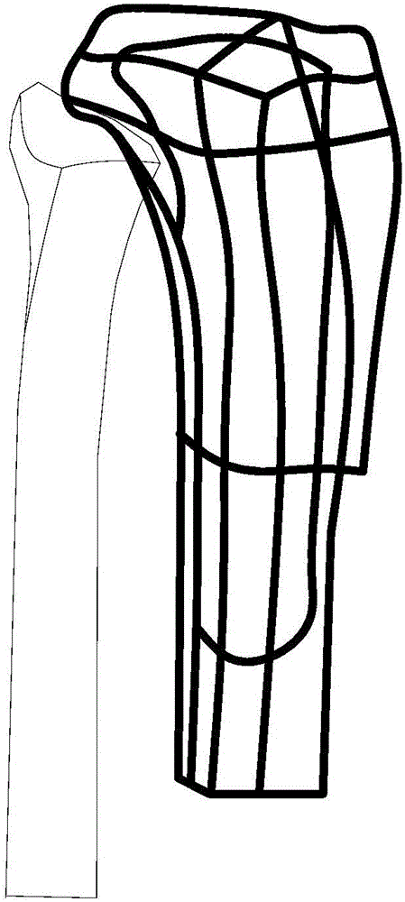
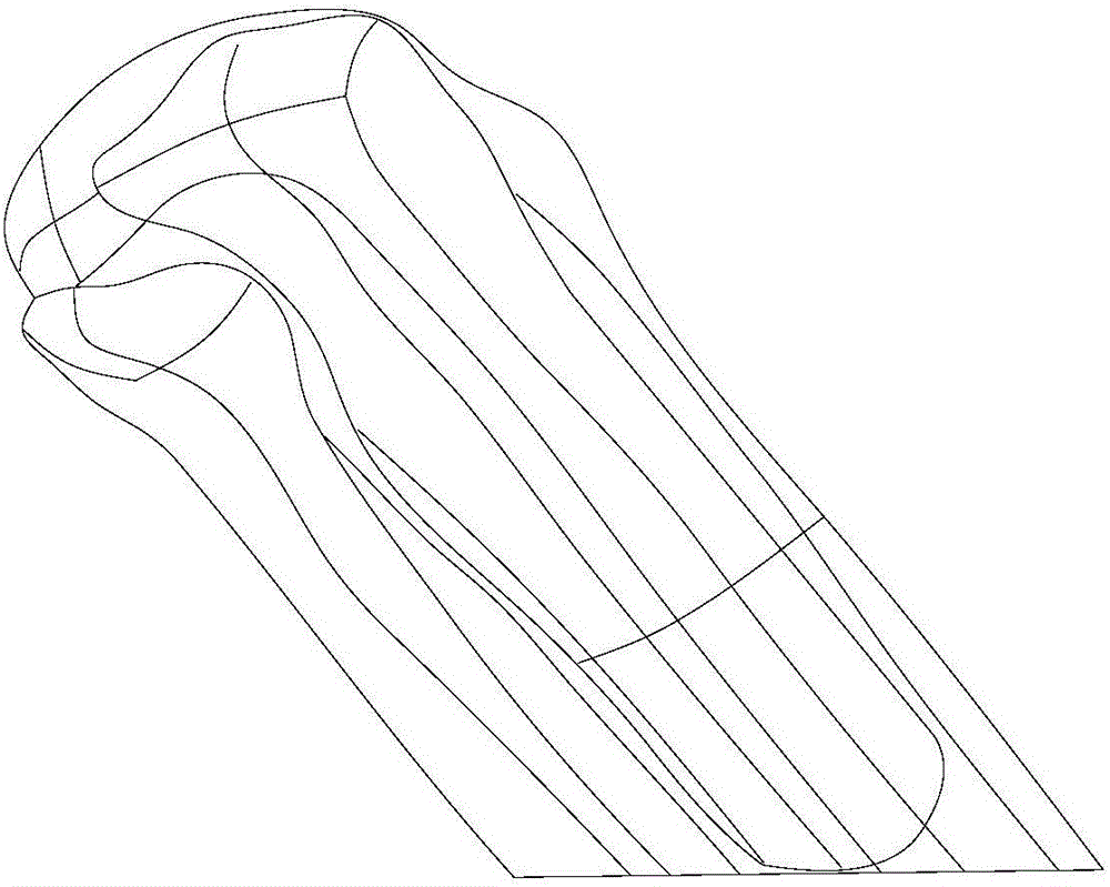
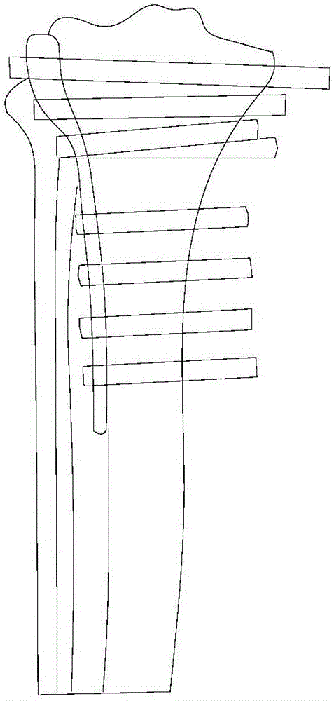
[0019] Such as Figure 1-Figure 5 as shown,

[0020] 1) Data acquisition: Use CT machine to scan both sides of the affected side and the healthy side of the patient, collect image files in Dicom format, and import them into medical 3D reconstruction software for 3D reconstruction;

[0021] 2) Use medical 3D reconstruction software to segment the image according to the CT scan data, reconstruct the bone 3D model, materialize it in the reverse engineering software and convert it into a solid model format file;

[0022] 3) Using computer-aided design CAD software, according to the three-dimensional reconstruction model of the bone, using the offset surface and trimming functions to accurately draw the irregular surface of the bone where the steel plate is placed, and design a steel plate that fits the bone on the healthy side. The mirror image function obtains the main body of the affected side plate, and at the same time combines the size and position of the bone fragments on t...


PUM


Abstract

The invention discloses a method for designing and forming an anatomical bone plate of an individualized bone model, which includes the following steps: 1) Data collection: use a CT machine to scan both sides of the affected side and the healthy side of the patient, and collect image files in Dicom format file, imported into medical 3D reconstruction software for 3D reconstruction; 2) using medical 3D reconstruction software, the image is segmented according to CT scan data, and bone 3D model reconstruction is carried out, which is materialized and converted into a solid model format file in reverse engineering software; 3) Use computer-aided design CAD software to reconstruct the model according to the three-dimensional bone. The design and forming method of the anatomical bone plate of the individualized skeletal model of the present invention can quickly customize an individualized anatomical internal fixation plate with a high bone matching degree according to different patients, different parts, and different fracture characteristics, so that the internal fixation plate of the patient The fixing plates are fully individualized and provide optimum fixing performance.

Description

technical field [0001] The invention relates to a method for designing and forming an anatomical bone plate of an individualized bone model. Background technique [0002] Fracture internal fixation is the technique of maintaining fracture alignment and stability with metal or biomaterials after fracture reduction through orthopedic surgery. The development of digital technology and medical imaging technology provides technical support for the preoperative planning and intraoperative implementation of orthopedic surgery. Precise personalized preoperative planning can reduce the subjective guesswork of empirical treatment, increase the success rate of surgical operation, and preoperative planning can also enable the surgeon to prepare the internal fixation implants required during the operation in advance. How to obtain the optimally designed internal fixation device model in the virtual environment is a key link in realizing precise orthopedic virtual surgery. The existing ...

Claims


Application Information

Patent Timeline
IPC IPC(8): A61B17/80A61B34/10B33Y10/00
CPCA61B17/80A61B2017/00526B33Y10/00
Inventor 黄文华邓羽平欧阳汉斌
Owner SOUTHERN MEDICAL UNIVERSITY
Learn More