Novel vertical-type processing operational center

An operation center and vertical technology, which is applied in the field of new vertical machining operation centers, can solve the problems of frequent maintenance of machining centers, increased machining costs, complex machining shapes, etc., to achieve stable overall structure, prolong service life, and ensure machining quality. Effect

Inactive Publication Date: 2016-08-03
新昌县羽林街道金敏轴承厂
View PDF0 Cites 6 Cited by
  • Summary
  • Abstract
  • Description
  • Claims
  • Application Information

AI Technical Summary

Problems solved by technology

[0002] Machining center, referred to as CNC, is a high-efficiency automatic machine tool for machining complex-shaped workpieces composed of mechanical equipment and a numerical control system. It is a highly mechatronic product. After the workpiece is clamped, the numerical control system can control the machine tool to automatically Selection, replacement of tools, automatic tool setting, automatic change of spindle speed, feed rate, etc., can continuously complete various processes such as drilling and tapping, thus greatly reducing the time of workpiece clamping, measurement and machine tool adjustment and other auxiliary processes. Parts with complex machining shapes, high precision requirements, and frequent replacement of varieties have good economic effects; there are many types of machining centers, which can be classified according to the relative position of the spindle and the worktable, and can be divided into horizontal machining centers, vertical machining centers and Universal machining center; the vertical machining center includes a workbench and a cross slide, and is equipped with a column, the machine head is hung on the column, and cantilevered for processing. This design method is only supported by the column, and the column is unilateral. Stress, it is easy to bend due to concentrated force, low rigidity, poor running stability, and also leads to frequent maintenance of the machining center, increasing processing costs

Method used


Image

  • Novel vertical-type processing operational center
  • Novel vertical-type processing operational center
  • Novel vertical-type processing operational center

Examples


Embodiment Construction

[0015] The following will clearly and completely describe the technical solutions in the embodiments of the present invention with reference to the accompanying drawings in the embodiments of the present invention. Obviously, the described embodiments are only some, not all, embodiments of the present invention. Based on the embodiments of the present invention, all other embodiments obtained by persons of ordinary skill in the art without making creative efforts belong to the protection scope of the present invention.

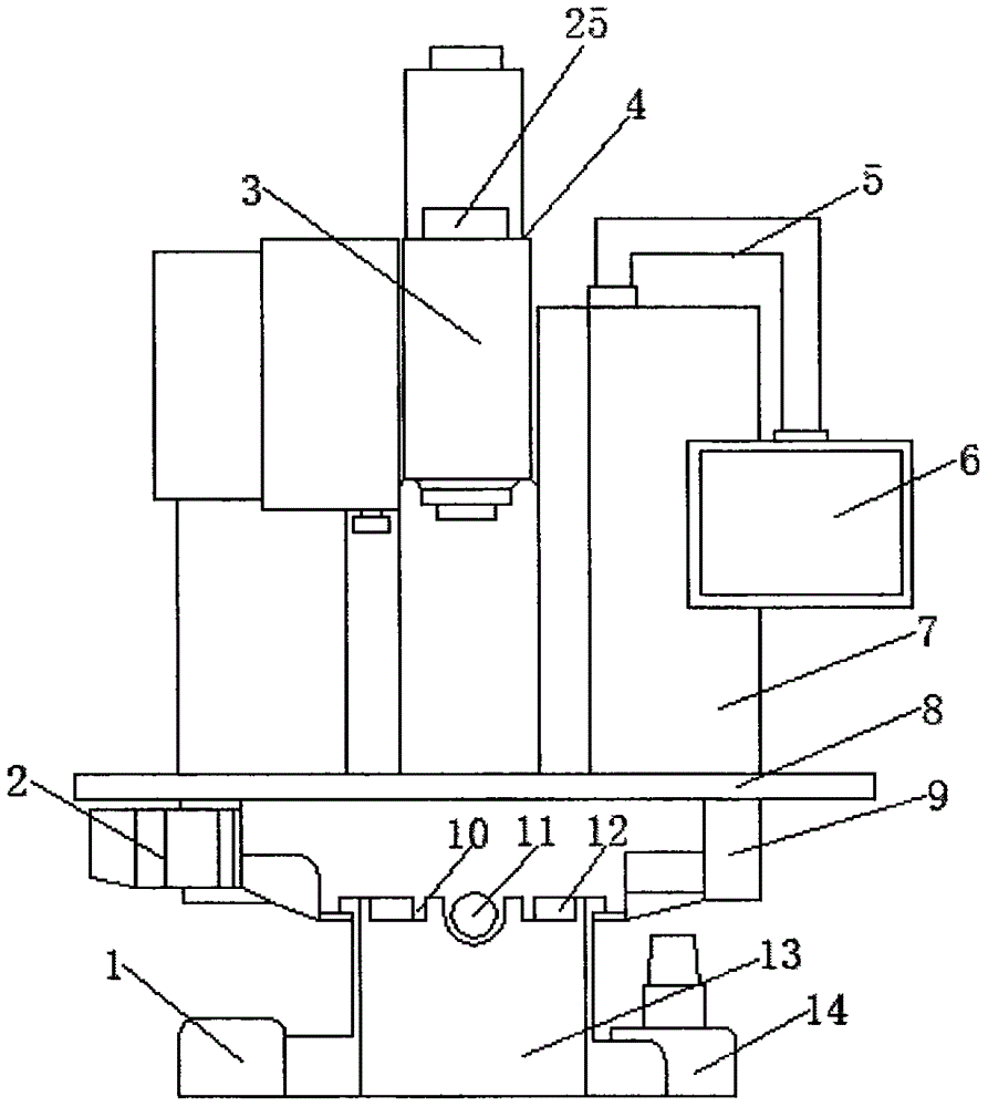
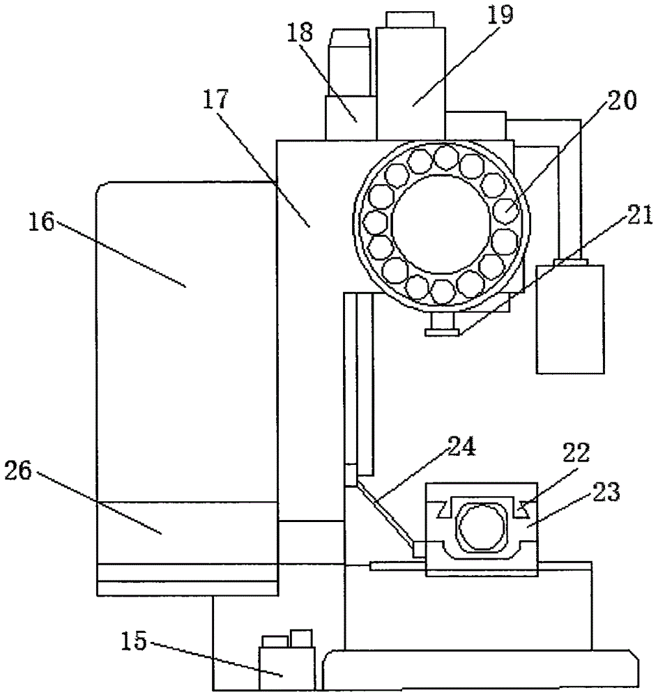
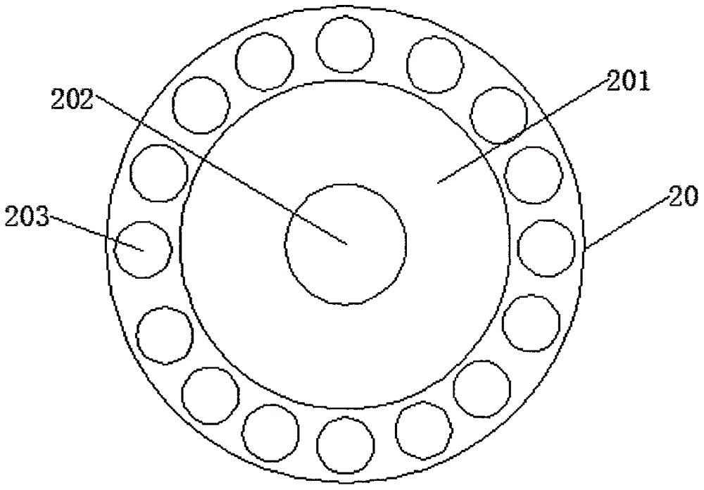
[0016] see Figure 1-3 , the present invention provides a technical solution: a novel vertical machining operation center, including an operation panel 6, a workbench 8, a cross slide 9, a base 13 and a tool magazine 20, the base 13 is fixedly connected to a column 17, and the column The bottom width of 17 is equal to the width of base 13, and the two together form an inverted T-shaped structure, which makes the overall structure more stable and can ensure the...


PUM


Abstract

The invention discloses a novel vertical machining operation center, which includes an operation panel, a workbench, a cross slide, a base and a tool magazine, the base and the column are fixedly connected, and the left and right sides of the base are respectively fixedly installed with cutting boxes and the cooling water tank, the base is provided with a Y-direction slide rail; the bottom of the cross slide table is fixedly welded with a Y-direction fixture, and the Y-direction fixture at the bottom of the cross slide table is movably connected with the Y-direction guide rail at the upper end of the base, and the cross slide A Y-direction screw is provided between the platform and the base, and a Z-axis servo motor is provided on one side of the cross slide. In this new type of vertical processing operation center, there is a shock absorber on the workbench. When the spindle motor drives the lifting cylinder to press down, the shock absorber plays a good buffer role, reducing the impact force of the manipulator on the workbench and prolonging the processing time. The service life of the center; the surface of the shock-absorbing pad is provided with anti-skid lines with a wavy structure, which has an anti-skid effect and prevents the workpiece from slipping off the workbench.

Description

technical field [0001] The invention relates to the technical field of mechanical processing equipment application, in particular to a novel vertical processing operation center. Background technique [0002] Machining center, referred to as CNC, is a high-efficiency automatic machine tool for machining complex-shaped workpieces composed of mechanical equipment and a numerical control system. It is a highly mechatronic product. After the workpiece is clamped, the numerical control system can control the machine tool to automatically Selection, replacement of tools, automatic tool setting, automatic change of spindle speed, feed rate, etc., can continuously complete various processes such as drilling and tapping, thus greatly reducing the time of workpiece clamping, measurement and machine tool adjustment and other auxiliary processes. Parts with complex machining shapes, high precision requirements, and frequent replacement of varieties have good economic effects; there are ...

Claims


Application Information

Patent Timeline
Patent Type & Authority Applications(China)
IPC IPC(8): B23Q1/01B23Q1/25B23Q11/00B23Q3/157B23Q11/12B23B19/00
CPCB23Q1/015B23Q1/25B23Q1/70B23Q3/157B23Q11/0032B23Q11/122
Inventor 竹洪燕石亚敏
Owner 新昌县羽林街道金敏轴承厂
Why Eureka
Try Eureka