Novel large-inertia rotating-shaft braking system

A brake system and large inertia technology, applied in the direction of axial brakes, brake types, fluid pressure actuators, etc., can solve the problems of long braking time, limited braking capacity, and limited travel of brake hydraulic cylinders, etc., to avoid Safety accidents, significant braking effect, and good system stability

Inactive Publication Date: 2016-08-03
GENERAL ENG RES INST CHINA ACAD OF ENG PHYSICS
View PDF6 Cites 2 Cited by
  • Summary
  • Abstract
  • Description
  • Claims
  • Application Information

AI Technical Summary

Problems solved by technology

[0004] The traditional braking system is mainly used in the braking of automobiles and trains with a rotating disc wheel structure, and its disadvantages are as follows: (1) The braking object is oriented to the rotating shaft with a small moment of inertia, and the braking of the rotating shaft with a large moment of inertia Its braking ability is limited; (2) The brake pad and the brake disc are in single-sided contact, and the friction surface is small, resulting in small braking force and long braking time; (3) The stroke of the brake hydraulic cylinder is limited, and the brake system is adapted to The thickness range of the brake disc is small, and it cannot adapt to brake discs of different thicknesses; (4) There is no device for detecting the wear of the brake pads, and when to replace the brake pads needs to be determined by a professional; (5) When starting to brake, the system has large vibration shock

Method used


Image

  • Novel large-inertia rotating-shaft braking system
  • Novel large-inertia rotating-shaft braking system
  • Novel large-inertia rotating-shaft braking system

Examples


Embodiment Construction

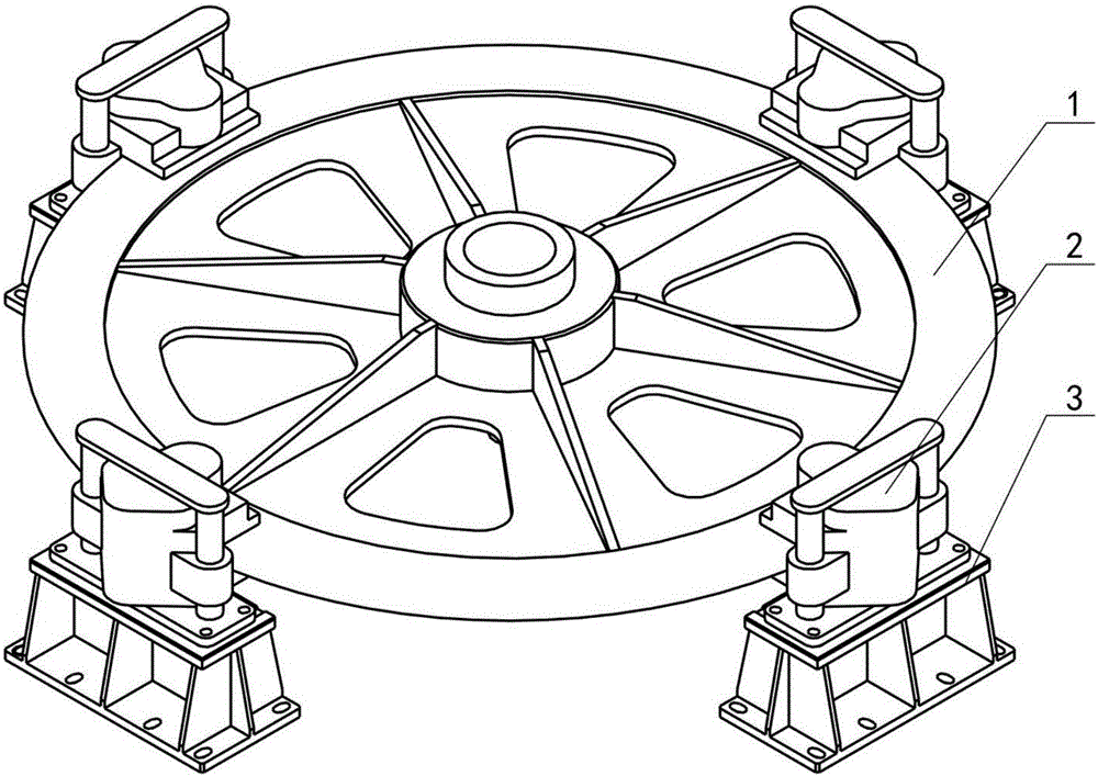
[0022] The present invention will be further described below in conjunction with accompanying drawing:

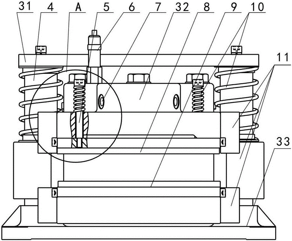
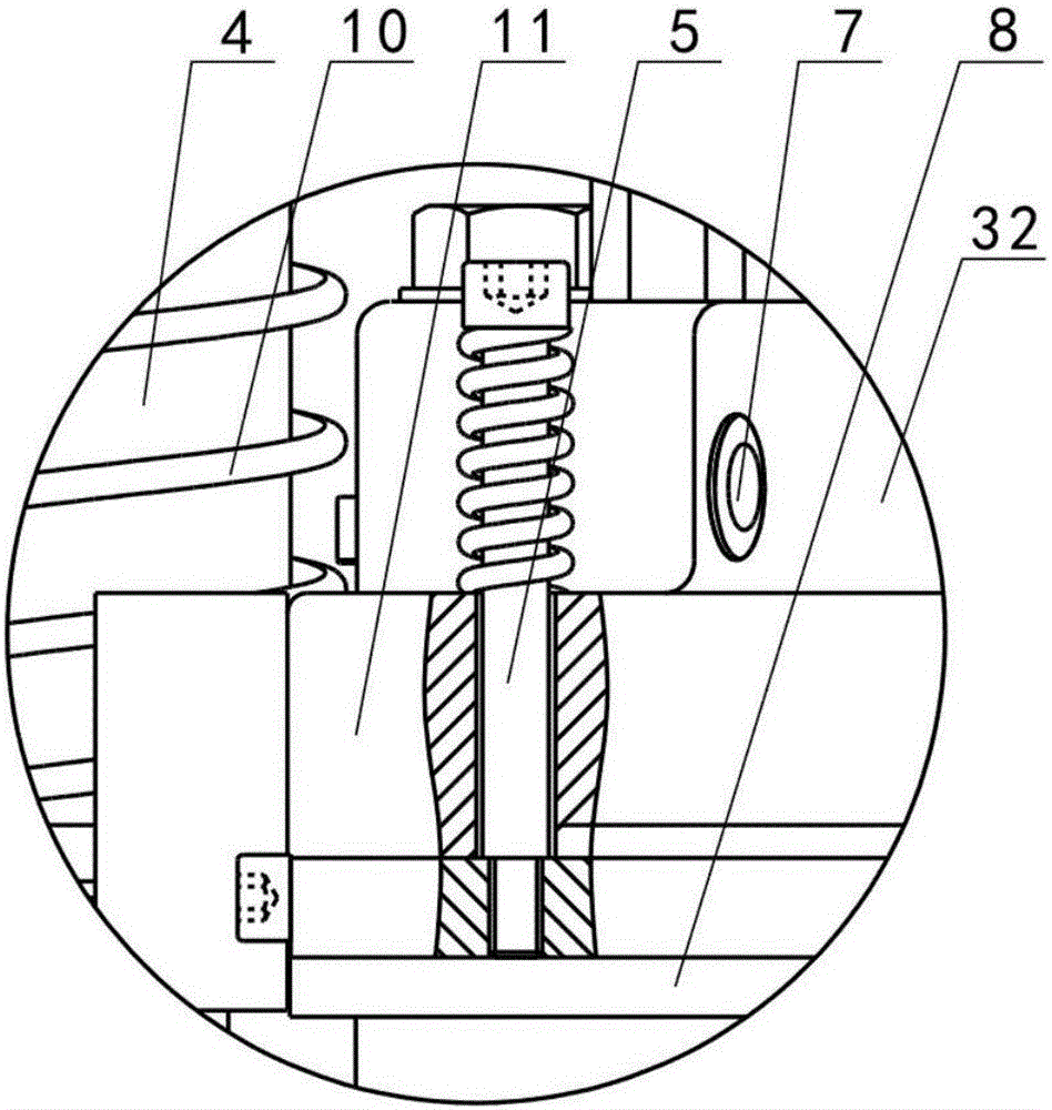
[0023] Such as figure 1 As shown, the novel large inertia rotating shaft brake system of the present invention includes a brake mounting bracket 3, a brake 2 and a brake disc 1, such as Figure 2-Figure 8 As shown, the brake 2 includes a mounting base 33, a guide column 4, a base body 11, a hydraulic cylinder 32, an upper brake pad 8, a lower brake pad 9 and a travel sensor 6, and the two guide columns 4 are vertically installed on the mounting base 33. The two ends of the base body 11 are respectively fitted on the two guide columns 4 through their own through holes and can move axially. The tops of the two guide columns 4 are fixedly connected by a connecting plate 31, and the hydraulic cylinder 32 is installed on the base body 11. The brake pad 8 is connected with the piston rod of the hydraulic cylinder 32 (not shown in the figure, which is a conventional structure), t...


PUM


Abstract

The invention discloses a novel large-inertia rotating-shaft braking system. The novel large-inertia rotating-shaft braking system comprises brake installing supports, brakes and a brake disc. In the brakes, guiding columns are installed on an installing base, the guiding columns are sleeved with base bodies, hydraulic cylinders and lower brake pads are installed on the base bodies respectively, upper brake pads are connected with piston rods of the hydraulic cylinders, and travel sensors are installed on the upper brake pads and used for detecting the thickness of the upper brake pads; the multiple brakes are installed on the multiple brake installing supports through installing bases of the brakes, the upper brake pads and the lower brake pads of all the brakes are located on the two sides of the brake disc respectively, and the multiple brakes are evenly distributed outside the circumference of the brake disc. According to the novel large-inertia rotating-shaft braking system, the multiple brakes are adopted, two brake pads are adopted for each brake, braking force is extremely large, the braking effect is quite remarkable, and the novel large-inertia rotating-shaft braking system is suitable for large-inertia rotating-shaft braking; the thickness of the brake pads is detected through the travel sensors in real time, and safety accidents caused by excessive abrasion failure of the brake pads are avoided.

Description

technical field [0001] The invention relates to a braking system for braking a rotating disc-wheel mechanism or system, in particular to a novel large-inertia rotating shaft braking system. Background technique [0002] The braking system is mainly used to brake the rotating disc-wheel mechanism or system to achieve the purpose of reducing or even stopping the speed of the disc-wheel mechanism or system; the kinetic energy conversion of the rotating wheel or disc during the entire braking process Slowing down or stalling is finally achieved for frictional heat. [0003] The traditional braking system mainly consists of four parts: drive system, control system, transmission system and brake. The driving system is divided into hydraulic drive, pneumatic drive, etc., which mainly provide power for the braking system; the control system receives and processes the signal of braking or not, and controls the driving system to provide power for the braking system; the transmission ...

Claims


Application Information

Patent Timeline
Patent Type & Authority Applications(China)
IPC IPC(8): F16D55/04F16D65/62F16D66/00F15B15/00
CPCF16D55/04F15B15/00F16D65/62F16D66/022
Inventor 张建全蒋春梅何阳宋琼余小勇
Owner GENERAL ENG RES INST CHINA ACAD OF ENG PHYSICS
Why Eureka
Try Eureka