Composite high-efficiency solar energy hot wind generation apparatus

A solar hot air generation device technology, applied in the field of solar energy utilization, can solve problems such as poor thermal conductivity, low hot air temperature, pollution, etc., and achieve the effects of improving thermal energy utilization, improving heat exchange efficiency, and increasing application range

Active Publication Date: 2016-08-03
北方瑞能(内蒙古)集团有限公司
View PDF5 Cites 1 Cited by
  • Summary
  • Abstract
  • Description
  • Claims
  • Application Information

AI Technical Summary

Problems solved by technology

[0002] Solar hot air drying is one of the modern drying methods, usually by blowing hot air into an oven or drying room to speed up the air flow; hot air drying requires a hot air source, and the traditional hot air generation method uses a fan to make the air around the heat source Make it blow to the surface of the heated object. The heat source here is usually provided by electric heating or burning coal, which usually consumes a lot of energy and causes a lot of pollution. It is not suitable for sustainable development.
[0003] The heat exchange medium used in conventional solar hot air technology is water, which has poor thermal conductivity, and the temperature of the hot air generated is low, making it difficult to achieve large-scale industrial application
[0004] As a clean and non-polluting new energy source, solar energy has been developed rapidly in recent years. However, in various new solar energy equipment, there are very few technologies and equipment related to the use of solar energy at medium temperature, which greatly limits the application field of solar energy.

Method used


Image

  • Composite high-efficiency solar energy hot wind generation apparatus

Examples


Embodiment 1

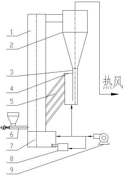
[0042] The bed material enters the main bed 1 after being heated to 280°C in the solar heater 5, and the air at 20°C

[0043] The fan 9 enters from the bottom of the main bed 1 through the air chamber 7, and the incoming air is heated by the bed material into hot air.

[0044] air, and the bed material is blown into the cyclone separator 2, and the bed material and hot air are realized in the cyclone separator 2

[0045] Air separator, the hot air is discharged from the top of the cyclone separator 2, the temperature of the hot air when discharged

[0046] The temperature is 260°C, and the bed material enters the solar heater 5 from the standpipe 3 and the feeder 4 for refilling.

[0047] hot.

Embodiment 2

[0049] The bed material enters the main bed 1 after being heated to 300°C in the solar heater 5, and the air at 15°C is

[0050] The fan 9 enters from the bottom of the main bed 1 through the air chamber 7, and the incoming air is heated by the bed material to become hot air.

[0051] And the bed material is blown into the cyclone separator 2, and the bed material and hot air are separated in the cyclone separator 2

[0052] Separator, the hot air is discharged from the top of the cyclone separator 2, and the temperature of the hot air when discharged is

[0053] At 290°C, the bed material enters the solar heater 5 from the standpipe 3 and the feeder 4 for reheating.


PUM


Abstract

The invention discloses a composite high-efficiency solar energy hot wind generation apparatus and belongs to the technical field of solar energy utilization. The composite high-efficiency solar energy hot wind generation apparatus is characterized in that a bed material feeding device is installed on a side wall of a main bed; an air chamber is mounted on the bottom of the main bed; the side wall of the air chamber is provided with an auxiliary combustion system; the main bed is communicated with a cyclone separator; a vertical pipe and a return feeder are orderly mounted on the bottom of the cyclone separator; the return feeder is communicated with the main bed via a solar energy heater; and a draught fan is respectively communicated with the air chamber, the auxiliary combustion system and the return feeder via pipelines. By the use of the composite high-efficiency solar energy hot wind generation apparatus, solar energy can be converted into hot wind of high quality; the composite high-efficiency solar energy hot wind generation apparatus is advantaged by simple structure, pollution avoidance, energy conservation and low cost, thereby being suitable for application to industrial drying and combustion systems.

Description

technical field [0001] The invention relates to the technical field of solar energy utilization, in particular to a composite high-efficiency solar hot air generating device. Background technique [0002] Solar hot air drying is one of the modern drying methods, usually by blowing hot air into an oven or drying room to speed up the air flow; hot air drying requires a hot air source, and the traditional hot air generation method uses a fan to make the air around the heat source Make it blow to the surface of the heated object. The heat source here is usually provided by electric heating or burning coal, which usually consumes a lot of energy and causes a lot of pollution, which is not suitable for sustainable development. [0003] The heat exchange medium used in conventional solar hot air technology is water, which has poor thermal conductivity, and the temperature of the hot air generated is relatively low, making it difficult to realize large-scale industrial application. ...

Claims


Application Information

Patent Timeline
Patent Type & Authority Applications(China)
IPC IPC(8): F24J2/04F26B21/00
CPCY02E10/44
Inventor 魏星方廷勇
Owner 北方瑞能(内蒙古)集团有限公司
Why Eureka
Try Eureka