Main shaft locking structure

A technology of locking structure and spindle, which is applied in the direction of clamping, supporting, positioning devices, etc., can solve problems such as insufficient rigidity, large wind resistance, long spindle wheelbase, etc., achieve smooth switching process, prolong service life and reduce friction Effect

Active Publication Date: 2016-08-10
GUANGZHOU HAOZHI ELECTROMECHANICAL
View PDF8 Cites 1 Cited by
  • Summary
  • Abstract
  • Description
  • Claims
  • Application Information

AI Technical Summary

Problems solved by technology

Disadvantages: The spring disc inside the main shaft is used as the brake pad and taper friction locking, the debugging and assembly process is complicated, and the hydraulic brake is often used due to insufficient pneumatic power, which is easy to cause leakage and other pollution; 2. The end tooth locking devices bite each other and Cone locking device for locking
Disadvantages: There are upper and lower matching end teeth arranged inside the main shaft, resulting in an excessively long wheelbase of the main shaft, and the high-speed tooth profile produces large wind resistance and noise, which cannot be used for high-speed and high-finish machining
Disadvantages: use the tool handle to simply connect the spindle or the static position on the machine tool spindle box, the locking effect is not good, and the rigidity is insufficient

Method used


Image

  • Main shaft locking structure
  • Main shaft locking structure
  • Main shaft locking structure

Examples


Embodiment Construction

[0028] Below, in conjunction with accompanying drawing and specific embodiment, the present invention is further described:

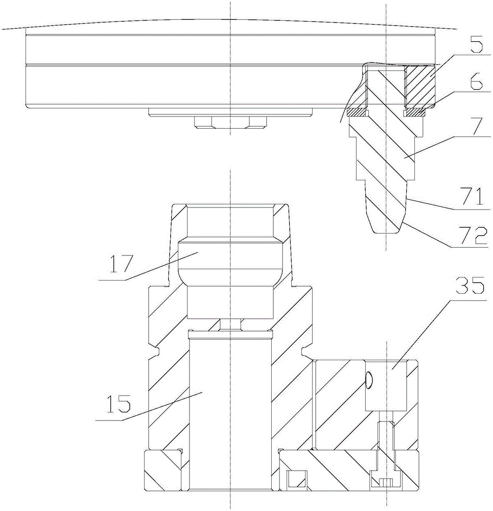
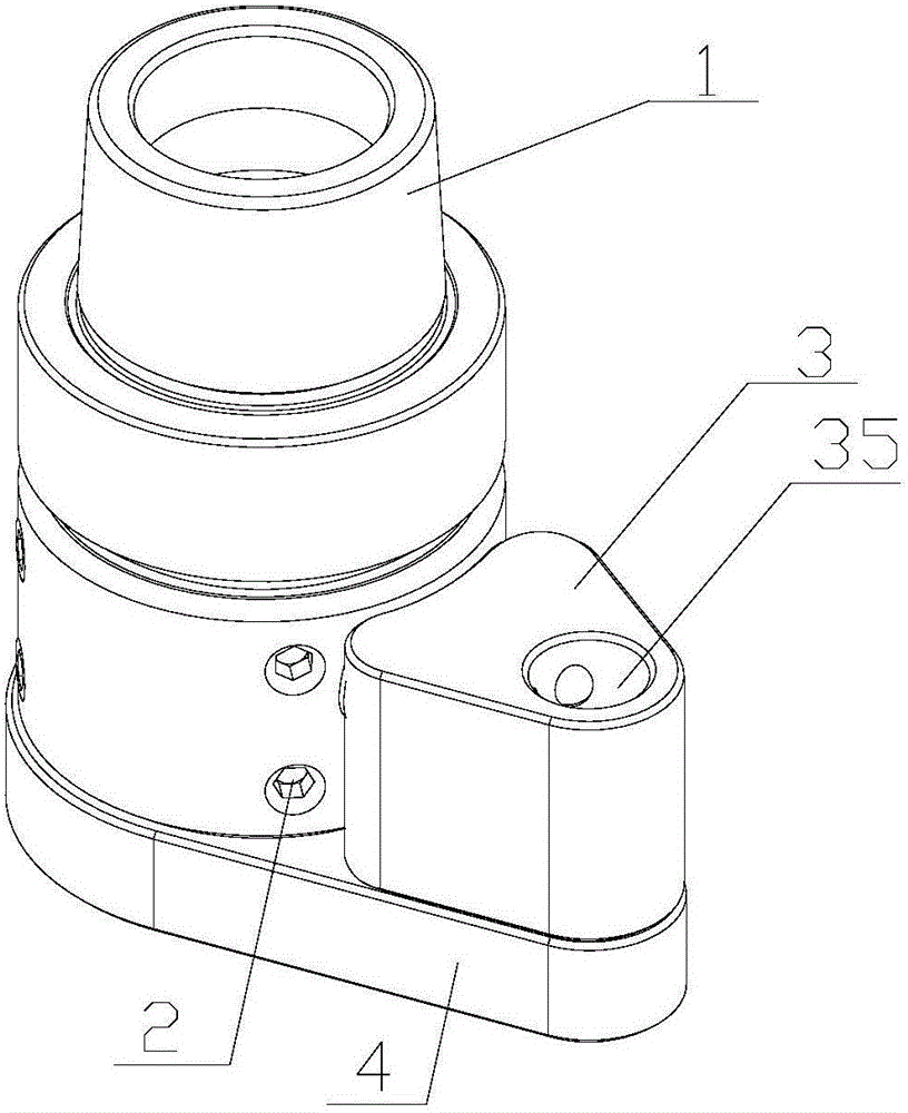
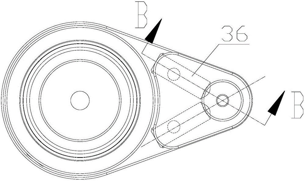
[0029] like Figure 1 to Figure 6 As shown, the spindle locking structure of the present invention includes a spindle, a limit pin 7 , a tool handle 1 and a limit block 3 . The main shaft is installed on the main shaft box 5, the main shaft includes a casing fixed on the main shaft casing 5 and a shaft core rotatably installed in the casing, the lower end of the shaft core is provided with an insertion hole; the limit pin 7 is fixed on the Below the casing or the spindle box 5, the lower end of the limit pin 7 forms a fixed head; the upper end of the tool handle 1 is inserted and fixed in the insertion hole, and the lower end of the tool handle 1 is provided with a tool installation hole 15; The limit block 3 is fixed on one side of the tool handle 1, and the upper end of the limit block 3 is provided with a first positioning hole 35, the first positio...


PUM


Abstract

The invention discloses a main shaft locking structure. The main shaft locking structure comprises a main shaft, a limiting pin, a knife handle and a limiting block, wherein the main shaft is mounted on a main shaft box; the main shaft comprises a housing fixedly arranged on the main shaft box and a shaft core which can be rotatably mounted in the housing; the lower end of the shaft core is provided with a plug-in mounting hole; the lower end of the limiting pin is formed with a fixed head; the limiting block is fixedly arranged at one side of the knife handle; the upper end of the limiting block is provided with a first positioning hole; the first positioning hole is positioned and matched with the fixed head while the knife handle is fixedly arranged on the shaft core; the inner part of the limiting block is further provided with two guide holes and two guide assemblies which are separately mounted in the two guide holes; each guide assembly comprises an elastic part and a steel ball, wherein the steel ball is clamped in an opening and is exposed in the first positioning hole. The main shaft locking structure is simple in debugging and assembly processes, can avoid generating leakage pollution, is small in noise, is long in service life, and is high in reliability.

Description

technical field [0001] The invention relates to a main shaft locking structure. Background technique [0002] With aerospace (aluminum alloy, titanium alloy), automobile, precision mold (graphite electrode, copper electrode), heavy industry (large casting, steel), 3C (aluminum alloy, plastic) and other representative industries, the processing efficiency (processing cost) ) and machining accuracy requirements, multi-axis linkage machine tools represented by turning and milling compound machining centers have achieved considerable development in recent years because they can complete various processes such as turning, milling, drilling, boring, and tapping in a single clamping. The emergence of the turning and milling compound machining center provides an effective solution for the machining accuracy and efficiency of the parts. Compared with the previous lathes and machining centers (or engraving and milling machines, drilling and tapping machines), the turning and milling,...

Claims


Application Information

Patent Timeline
IPC IPC(8): B23B19/02B23Q3/12
CPCB23Q1/70B23Q3/12
Inventor 雷群郑绍坚候宗毅
Owner GUANGZHOU HAOZHI ELECTROMECHANICAL
Why Eureka
Try Eureka