Minimal quantity lubricating system device

A system device, micro-lubrication technology, applied in metal processing machinery parts, maintenance and safety accessories, metal processing equipment, etc., can solve the problems of large volume, difficult control of oil mist consumption and oil droplet size, complex structure, etc., and achieve the goal of using Simple, compact, avoid application effects

Active Publication Date: 2016-08-10
东台城东科技创业园管理有限公司
View PDF13 Cites 11 Cited by
  • Summary
  • Abstract
  • Description
  • Claims
  • Application Information

AI Technical Summary

Problems solved by technology

[0005] Aiming at the deficiencies in the prior art that the amount of oil mist and the size of oil droplets are difficult to control, the structure is complex, and the volume is large, the present invent

Method used


Image

  • Minimal quantity lubricating system device
  • Minimal quantity lubricating system device
  • Minimal quantity lubricating system device

Examples


Embodiment Construction

[0030] The present invention will be further described below in conjunction with the accompanying drawings and specific embodiments, but the protection scope of the present invention is not limited thereto.

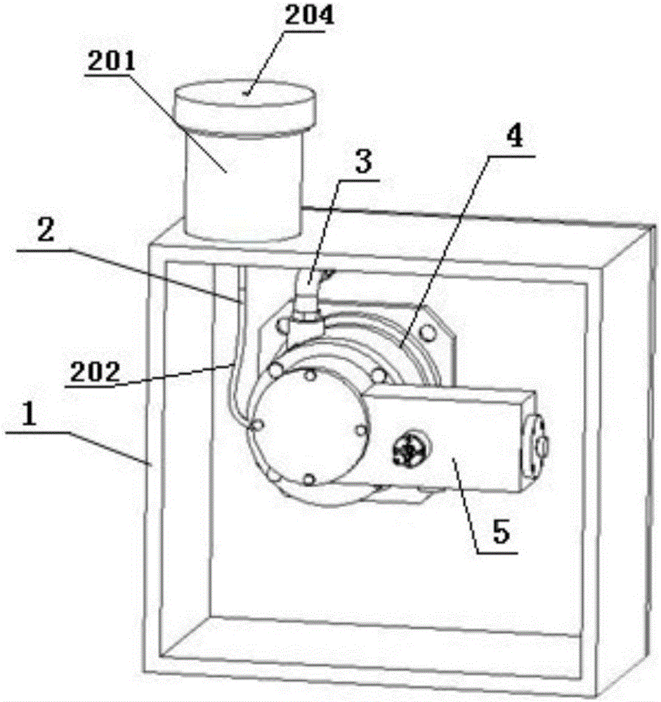
[0031] Such as figure 1 As shown, a minimal quantity lubrication system device includes a box body 1, an oil system 2, an air system 3, a power system 4 and an injection system 5; the oil system 2, the air system 3, the power system 4 and the injection system System 5 is mounted on box 1 . The oil system 2 includes a fuel tank 201, a conduit 202 and an oil hose 203; the fuel tank 201 is fixed on the top of the tank 1; the upper cover of the fuel tank 201 has a small hole 204; the bottom of the fuel tank 201 is connected to the conduit 202 , the end of the conduit 202 is connected with an oil hose 203 .

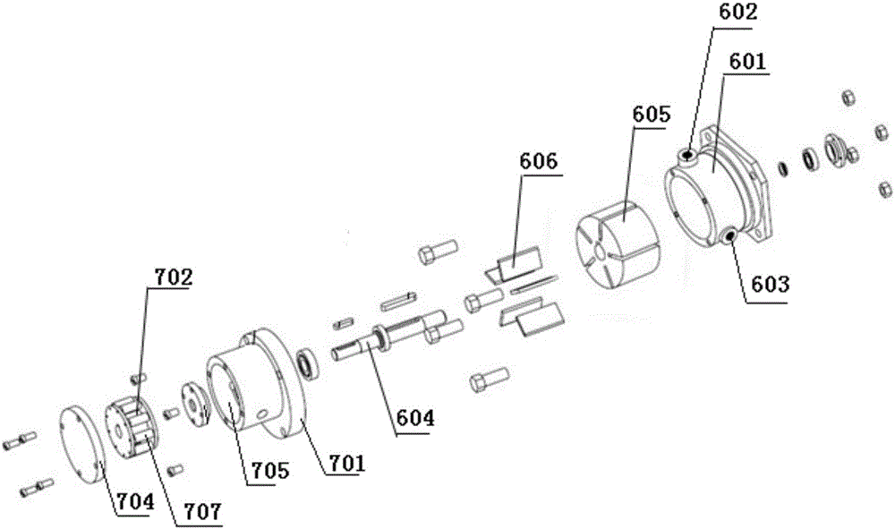
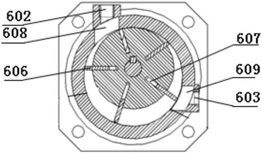
[0032] Such as figure 2 with image 3 As shown, the power system 4 includes an air motor 6 and an oil drive component 7; the air motor 6 is installed on the side pla...


PUM

PropertyMeasurementUnit
Central angleaaaaaaaaaa

Abstract

The invention provides a minimal quantity lubricating system device. The device comprises a box, an oil way system, a gas way system, a power system and an injection system. The power system comprises a pneumatic motor and an oil liquid driving assembly. The oil liquid driving assembly comprises a driving base, a rolling body, a sleeve and an end cap B. The oil way system comprises an oil tank, a guide pipe and an oil liquid hose. The gas way system comprises a connector A, a gas flow regulating valve, a gas pipe A, a connector B, a connector C and a check valve. The injection system comprises an injection valve body, a piston, an oil amount regulating handle and an end cap A. The pressure of lubricating oil is regulated by rotating the oil amount regulating handle, so that the injection speed and the oil drop size of the lubricating oil are changed. The flow of compressed air is regulated by rotating the gas flow regulating valve, so that the oil amount of the lubricating oil is changed. The minimal quantity lubricating system device is compact in structure and easy to use, and does not need a power source. The industrial commonly used 0.8-1 MPa compressed air is used as a power source, the oil amount and oil drop size can be regulated, and the minimal quantity lubricating system device can be used for general production fields or anti-explosion special environment.

Description

technical field [0001] The invention belongs to the technical field of cutting processing, and in particular relates to a minimal quantity lubrication system device. Background technique [0002] In traditional mechanical processing, a large amount of pouring cutting fluid is usually supplied to achieve the functions of flushing chips, reducing the temperature of the cutting zone, and prolonging the tool life. However, the use of a large amount of cutting fluid not only increases the manufacturing cost, but also pollutes the The environment has endangered the health of employees. Under the sustainable development strategy, the country has stricter requirements on environmental pollution, and the processing cost of cutting fluid is also higher and higher. [0003] Minimal Quantity Lubrication (MQL) technology is to reduce the amount of cutting fluid as much as possible under the premise of ensuring effective lubrication. It lubricates the cutting point by spraying tiny drop...

Claims


Application Information

Patent Timeline
IPC IPC(8): B23Q11/10
CPCB23Q11/1046
Inventor 裴宏杰陈少峰陈林峰李公安付坤鹏王贵成
Owner 东台城东科技创业园管理有限公司
Why Eureka
Try Eureka