Unbonded prestress and steel-concrete composite reinforcement design method for concrete T-shaped beams
A design method and concrete structure technology, applied in bridge reinforcement, bridge construction, bridge, etc., can solve problems such as high investment cost, difficult maintenance, and reduction of resonance effect between prestressed tendons and structures
- Summary
- Abstract
- Description
- Claims
- Application Information
AI Technical Summary
Problems solved by technology
Method used
Image

Examples
Embodiment Construction
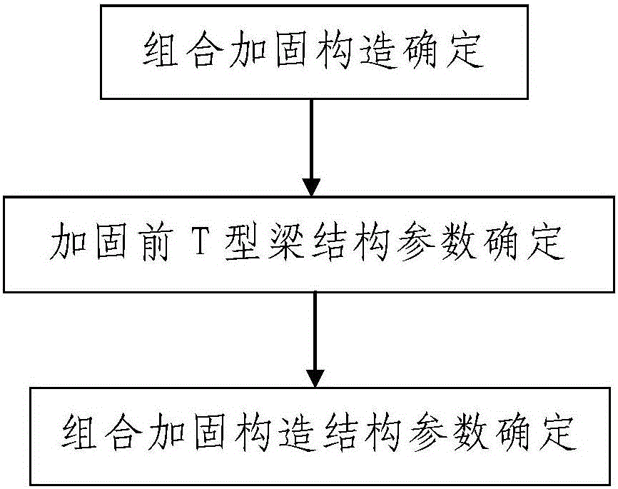
[0092] Such as figure 1 The unbonded prestressed and steel-concrete combined reinforcement design method of a concrete T-beam shown includes the following steps:
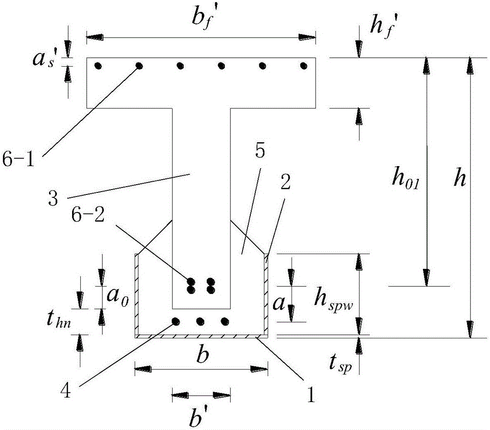
[0093] Step 1. Combination reinforcement structure determination: determine the unbonded prestressed and steel plate-concrete composite reinforcement structure of the reinforced T-beam 3; the reinforced T-beam 3 is a reinforced concrete beam;
[0094] Such as figure 2 As shown, the combined reinforcement structure of unbonded prestress and steel plate-concrete includes a bottom steel plate 1 arranged under the area to be reinforced of the T-beam 3 to be reinforced, and two steel plates arranged on the left and right sides of the area to be reinforced respectively. The longitudinal side steel plates 2 and two end-blocking steel plates respectively arranged at the front and rear ends of the area to be reinforced, the bottom steel plate 1 and the two longitudinal side steel plates 2 are arranged in the longitudinal b...
PUM
 Abstract
Description
Claims
Application Information