Utilization system of dead steam heat of power plant

A technology of steam heat and power plants, which is applied in the direction of steam application, steam engine device, fluid heater, etc. It can solve the problem that it is not suitable for heating units, there is no guidance document for exhaust steam waste heat recovery projects, and exhaust steam waste heat recovery projects have not been fully developed. expected utility

Inactive Publication Date: 2016-08-10
中国大唐集团科学技术研究总院有限公司
View PDF5 Cites 7 Cited by
  • Summary
  • Abstract
  • Description
  • Claims
  • Application Information

AI Technical Summary

Problems solved by technology

[0002] Under the general trend of energy saving and emission reduction, it is imperative to recover waste heat from exhaust steam of heating units in thermal power plants. There are more and more waste heat projects in power plants, and the investment in this optimized design of heating units is huge.
Moreover, most of the exhaust steam waste heat recovery projects that have been completed have not played the expected effect in actual operation, and most of the exhaust steam waste heat projects are not suitable for the existing heating units during design and operation.
Up to now, there is no guidance document in the industry for waste steam waste heat recovery projects in power plants

Method used


Image

  • Utilization system of dead steam heat of power plant

Examples


Embodiment Construction

[0014] The specific embodiments of the present invention will be described in further detail below in conjunction with the drawings and embodiments. The following examples are used to illustrate the present invention, but not to limit the scope of the present invention.

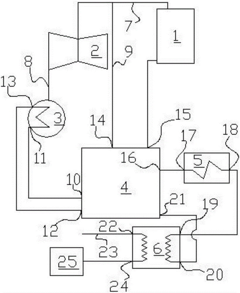
[0015] See figure 1 , A power plant exhaust steam heat utilization system according to a preferred embodiment of the present invention includes a boiler 1, a steam turbine 2, a condenser 3, a heat pump 4, a peak heater 5 and a secondary heat exchange station 6. The boiler 1 is connected to the steam turbine 2 through an intake pipe 7, the steam turbine 2 is connected to the condenser 3 through an exhaust pipe 8, and an extraction pipe 9 is connected to the intake pipe 7 of the steam turbine 2, and the condensing steam The heat pump has a water outlet and a water return port. The heat pump has a low temperature heat source inlet, a low temperature heat source outlet, a driving heat source inlet, and a condensate...


PUM


Abstract

The invention relates to a utilization system of dead steam heat of a power plant. The utilization system comprises a boiler, a steam turbine, a condenser, a heat pump, a peak load calorifier and a secondary heat exchange station, wherein the steam turbine is connected with the condenser through an exhaust pipe; a steam extraction pipe is arranged on an air inlet pipe of the steam turbine; a low temperature heat source inlet of the heat pump is connected with a water outlet of the condenser; a lower temperature heat source outlet of the heat pump is connected with a water return port of the condenser; a driving heat source inlet of the heat pump is connected with the steam extraction pipe; a condensate outlet of the heat pump is connected to the boiler; a water supply outlet of the heat pump is connected with a water inlet of the peak load calorifier; a water outlet of the peak load calorifier is connected with a heat source inlet of the secondary heat exchange station through a pipeline; a heat source outlet of the secondary heat exchange station is connected with a water supply inlet of the heat pump; a water inlet of the secondary heat exchange station is connected with a water supply source; and a water outlet of the secondary heat exchange station is connected with a heat utilization device. The utilization system can well adapt to an existing power plant heat supply unit and can utilize dead steam waste heat of the steam turbine, thereby achieving the purposes of energy conservation and consumption reduction.

Description

Technical field [0001] The invention relates to the technical field of waste heat recovery in thermal power plants, and in particular to a technology for recovering waste heat from exhaust steam of a steam turbine. Background technique [0002] Under the general trend of energy conservation and emission reduction, it is imperative to recover waste heat from the exhaust steam of heat supply units in thermal power plants. There are more and more waste heat projects of waste steam in power plants, and the investment in this optimized design of heat supply units is huge. Moreover, most of the exhausted steam waste heat recovery projects that have been implemented and completed did not play the expected effect in actual operation, and most of the exhausted steam waste heat projects were not suitable for existing heating units during design and operation. Up to now, no guidance documents have been issued for waste heat recovery projects of power plants in the industry. [0003] In view ...

Claims


Application Information

Patent Timeline
Patent Type & Authority Applications(China)
IPC IPC(8): F01K17/00F01K17/02F24H4/02
CPCF01K17/005F01K17/02F24H4/02
Inventor 张孝勇赵文波
Owner 中国大唐集团科学技术研究总院有限公司
Why Eureka
Try Eureka