

Dynamics modeling method for obtaining antenna on-track vibration influence
A technology of dynamic modeling and vibration influence, applied in simulators, instruments, control/regulation systems, etc., can solve the problems of lack of modeling and simulation, and achieve the effect of effective separation
- Summary
- Abstract
- Description
- Claims
- Application Information
AI Technical Summary
Problems solved by technology
Method used
Image

Examples
Embodiment 1
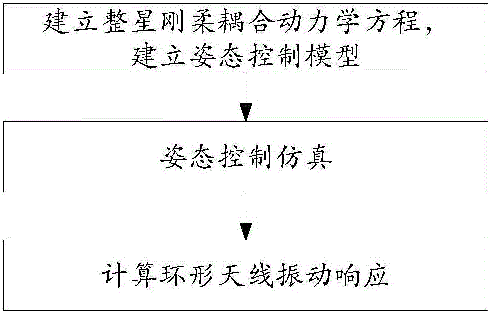
[0083] Embodiment 1. A dynamic modeling method for obtaining the influence of antenna on-orbit vibration, such as figure 1 shown, including the following steps:
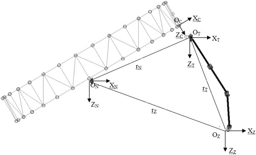
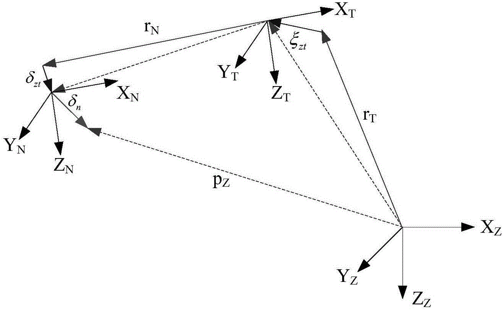
[0084] Step (1) The loop antenna in the shaping system and the extended arm used to support the loop antenna are used as substructures, and the rigid-flexible coupling dynamic equations of the whole star system are established, including the translational motion equation of the center of mass of the whole star system, the system around the center of mass The rotation motion equation of the arm, the vibration equation of the rigid loop antenna with the extended arm, the vibration equation of the loop antenna itself, the +Y axis and -Y axis vibration equations of the solar wing, where the Y axis is the center of mass of the system established with the center of mass of the whole star as the origin The Y axis of the coordinate system.
[0085] The rigid-flexible coupled dynamic equations of the whole star system specif...
PUM
 Abstract
Description
Claims
Application Information