Supercharge Your Innovation With Domain-Expert AI Agents!

A gate driving unit, a row gate scanning driver and a driving method thereof

A gate drive and row gate technology, applied in the direction of instruments, static indicators, etc., can solve the problems of reducing circuit switching speed, complex circuit structure, and increased internal wiring, so as to reduce power consumption, improve circuit efficiency, reduce Effect of Clock Voltage Swing

Active Publication Date: 2018-06-22
王磊 +1
View PDF6 Cites 0 Cited by
  • Summary
  • Abstract
  • Description
  • Claims
  • Application Information

AI Technical Summary

Problems solved by technology

[0003] New oxide thin film transistor devices have become popular research objects in recent years because of their excellent performance and simple manufacturing process. However, oxide thin film transistors are N-type devices with negative threshold voltage characteristics. If transistors with positive threshold voltage characteristics are used The developed row scanning circuit will cause the power consumption of the circuit to increase sharply or even fail to work properly because the oxide thin film transistor cannot be completely turned off.
In order to completely turn off the oxide thin film transistor, most of the new line scan driving circuits will use two or more negative power supplies inside, but multiple negative power supplies will make the circuit structure more complicated, the internal wiring will increase, and the circuit area will be reduced. increases, and the requirements for each power supply are also more stringent
In addition, most line scanners use AC clock signals to provide output current, and the parasitic capacitance of the output transistor will not only consume considerable power consumption, but also reduce the switching speed of the circuit due to charging and discharging

Method used


Image

  • A gate driving unit, a row gate scanning driver and a driving method thereof
  • A gate driving unit, a row gate scanning driver and a driving method thereof
  • A gate driving unit, a row gate scanning driver and a driving method thereof

Examples


Embodiment

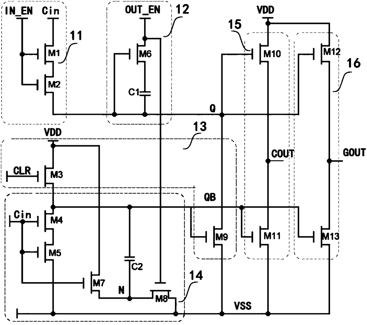
[0042] Such as figure 1 As shown, a gate drive unit is composed of a signal acquisition module 11, a boost module 12, an inverter module 13, a negative pressure module 14, an internal output module 15 and a scan output module 16. The gate drive unit The control signal includes the first clock input port IN_EN, the second clock input port OUT_EN, the third clock input port CLR, the first power port VDD, the second power port VSS, the signal collection port Cin, the first output port COUT and the second output port port GOUT;

[0043] The signal acquisition module 11 is composed of first and second transistors. The drain of the first transistor M1 is connected to the signal acquisition port Cin, its source is connected to the drain of the second transistor M2, and its gate is connected to the second transistor M2 respectively. The gate of is connected to the first clock input port IN_EN;

[0044] The boost module 12 is composed of a sixth transistor M6 and a first storage capa...


PUM


Abstract

The invention discloses a gate drive unit, a row gate scan driver and a drive method thereof. The gate drive unit is composed of a signal acquisition module, a boost module, an inverter module, a negative pressure module, an internal output module and a scan output module Composition, through the negative voltage module, the gate drive unit can work normally only with a single negative power supply, which simplifies the circuit structure and reduces the circuit area, while reducing the clock jump swing and reducing the power consumption of the circuit. In addition, the output module adopts DC The driving method can reduce dynamic power consumption and improve response speed. After the multi-level gate drive units are connected in series and connected with the corresponding power supply and timing control module, a row gate scan driver is formed. The driver only needs 3 drive clocks to realize the shift output of the gate drive signal, and all clocks are It is a pipelined driving sequence with a duty cycle of 33.3%. The timing is simple and independent, avoiding competition risks and improving circuit stability.

Description

technical field [0001] The invention relates to the field of row grid scanning of an active matrix light-emitting flat panel display, in particular to a grid driving unit, a row grid scanning driver and a driving method thereof. Background technique [0002] The traditional display panel row gate drive circuit requires a special drive chip, and the chip is crimped on the glass substrate to drive the pixel circuit through the process. In recent years, with the development of technology, the row integration technology, which uses thin film transistors to directly integrate row gate drive circuits in display panels instead of driver chips, has become a hot topic in current research. In line integration technology, the gate drive circuit and the pixel circuit are integrated in the same array, which can avoid the timing disorder caused by the difference in signal trace length through layout and wiring, and improve the signal quality; it can also reduce the substrate area and proc...

Claims


Application Information

Patent Timeline
Patent Type & Authority Patents(China)
IPC IPC(8): G09G3/3225
CPCG09G3/3258G09G3/32G09G3/20
Inventor 吴为敬胡宇峰李冠明徐苗王磊彭俊彪
Owner 王磊
Features
  • R&D
  • Intellectual Property
  • Life Sciences
  • Materials
  • Tech Scout
  • Unparalleled Data Quality
  • Higher Quality Content
  • 60% Fewer Hallucinations
Learn More