Solar cell luminescent plate and manufacture method therefor

A technology of solar cells and solar cells, which is applied in the direction of electric light sources, semiconductor devices of light-emitting elements, circuits, etc., can solve problems such as inconvenient detection, reverse electrode installation, and desoldering of wires, so as to improve reliability and production efficiency. Reduce the difficulty of assembly and avoid the effect of false welding

Active Publication Date: 2016-08-10
JIAWEI RENEWABLE ENERGY CO LTD
View PDF8 Cites 4 Cited by
  • Summary
  • Abstract
  • Description
  • Claims
  • Application Information

AI Technical Summary

Problems solved by technology

[0004] The technical problem to be solved by the present invention is to provide a solar cell light-emitting panel and its preparation method, aiming to solve the problem that in the prior art, the components are connected by wires, and false soldering, missing soldering, and wire desoldering are prone to occur during manual assembly. And the electrode is installed reversely, and the detection is inconvenient and other defects

Method used


Image

  • Solar cell luminescent plate and manufacture method therefor
  • Solar cell luminescent plate and manufacture method therefor
  • Solar cell luminescent plate and manufacture method therefor

Examples


Embodiment 1

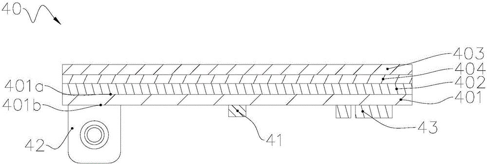
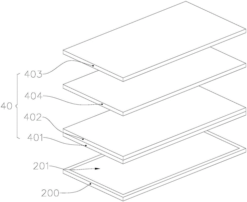
[0042] Such as figure 1 and 2 As shown, in this embodiment, polycrystalline silicon solar cells or traditional monocrystalline silicon solar cells are used as an example to illustrate the production of solar cell light-emitting panels 40. It should be noted that the traditional monocrystalline silicon solar cells referred to here are Refers to monocrystalline silicon solar cells other than those produced by Sunpower.

[0043] 1. Fabrication of the circuit substrate 401 , the circuit substrate 401 of this embodiment is a single-sided board.

[0044] In this embodiment, the circuit substrate 401 has a front side (ie, the first surface 401a in the figure, hereinafter referred to as the first surface 401a) and a back side (ie, the second surface 401b in the figure, hereinafter generally referred to as the second surface 401b), Print solder resist ink (not shown) on the second surface 401b to form pad positions (not shown), bake and solidify to obtain a circuit substrate 401 with...

Embodiment 2

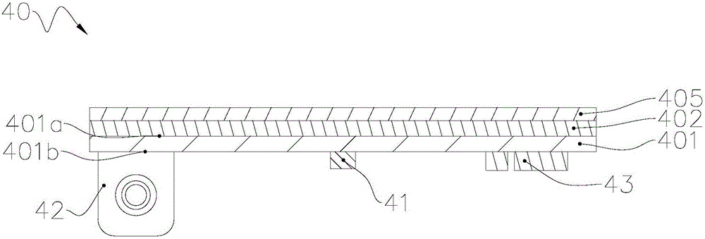
[0052] Attached below image 3 and 4 , only the differences from Embodiment 1 will be described in detail.

[0053] Such as image 3 and 4 As shown, in this embodiment, the fabrication of the solar cell light-emitting panel 40 is described by taking the Sunpower monocrystalline silicon cell as an example.

[0054] 1. Fabrication of the circuit substrate 401 , the circuit substrate 401 of this embodiment is double-sided.

[0055] In this embodiment, the circuit substrate 401 prints solder resist ink (not shown) on both the first surface 401a and the second surface 401b to form pad positions, and after baking and curing, a patterned circuit layer is obtained on both surfaces ( not shown in the figure) circuit substrate 401. This process is well known to those skilled in the art and will not be described in detail here.

[0056] 2. Packaging of electronic components including LEDs.

[0057] For the pad position of the circuit substrate 401, use a stencil printing solder pa...


PUM


Abstract

The invention relates to a solar cell luminescent plate and a manufacture method therefor. The solar cell luminescent plate provided in the invention comprises a line substrate, an LED lamp bead and a solar cell sheet. The line substrate comprises a first surface and a second surface opposite to the first surface, wherein the LED lamp bead is encapsulated on the second surface, and the solar cell sheet is arranged on the first surface. The solar cell sheet and the line substrate are integrated to form the solar cell luminescent plate. Compared with technologies of the prior art, the solar cell luminescent plate provided in the invention is advantageous in that convenience of assembling is realized; pseudo soldering, missing soldering, conductor unsoldering reverse installation of electrodes and the like can be prevented because conductor connection is not needed; convenience of detection and maintenance can be realized. Via use of the solar cell luminescent plate manufacture method provided in the invention, solar cell luminescent plate assembling difficulty is lowered, and product reliability and production efficiency are improved.

Description

technical field [0001] The invention relates to the technical field of photovoltaic components, in particular to a solar cell luminous panel and a preparation method thereof. Background technique [0002] Lawn lights are widely used in urban slow lanes, narrow lanes, residential areas, tourist attractions, parks, squares, private gardens, courtyard corridors and other public places to improve the safety and appreciation of people's night travel, and can also change people's mood. To stabilize people's emotions, its design mainly pursues the integration of appearance and surrounding environment, and the lighting is relatively soft. [0003] At present, the traditional solar lawn is combined with solar panels and light-emitting devices to save energy without consumption, and is not limited by geographical regions, such as the "human body induction lawn lamp" "A solar silicon wafer is arranged on the lamp cover, a solar controller is installed inside the lamp cover, and multip...

Claims


Application Information

Patent Timeline
IPC IPC(8): H01L31/048H01L31/05F21S9/03F21V23/00F21V23/06F21Y115/10
CPCY02E10/50H01L31/048F21S9/03F21S9/032F21V23/00F21V23/06H01L31/05H01L31/0504
Inventor 邹知傧陈国强刘琦刘俊显
Owner JIAWEI RENEWABLE ENERGY CO LTD
Why Eureka
Try Eureka