Eureka AIR delivers breakthrough ideas for toughest innovation challenges, trusted by R&D personnel around the world.

Method for reducing height of base station antenna, and base station antenna

A base station antenna and antenna technology, which is applied to antennas, antenna components, antenna supports/mounting devices, etc., can solve problems affecting antenna performance, antenna matching is difficult, and antenna gain is reduced, so as to achieve high production efficiency and save energy. The effect of reducing costs and reducing processes

Inactive Publication Date: 2016-08-10
SHENZHEN SAMSUNG COMM TECH RES +1
View PDF2 Cites 21 Cited by
  • Summary
  • Abstract
  • Description
  • Claims
  • Application Information

AI Technical Summary

Problems solved by technology

However, the existence of this distance also leads to an increase in the height of the antenna. In order to effectively reduce the height of the antenna, people mostly conduct related research from the perspective of the antenna oscillator. However, the decrease in the height of the oscillator will greatly affect the performance of the antenna. , the main performance is that the matching of the antenna is more difficult to achieve, and the gain of the antenna will be reduced

Method used


Image

  • Method for reducing height of base station antenna, and base station antenna
  • Method for reducing height of base station antenna, and base station antenna
  • Method for reducing height of base station antenna, and base station antenna

Examples


Embodiment 3

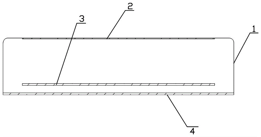
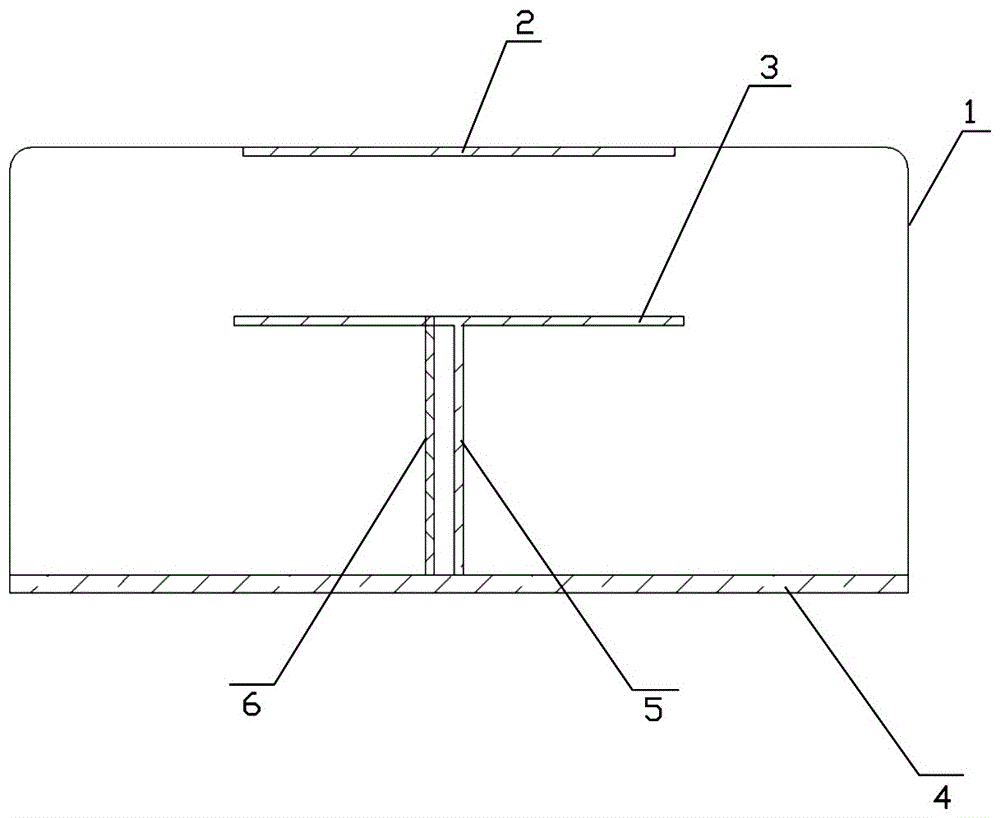
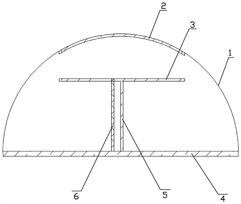
[0047] The antenna involved in this embodiment is a parasitic radiation dipole base station antenna, which is mainly composed of a radome 1 , a parasitic radiation sheet 2 , a dipole PCB 3 , a reflector 4 , a metal base 5 and a feeder cable 6 . Wherein: the parasitic radiation sheet 2 is attached to the inner side of the radome 1 and is arranged as a whole with the radome 1, and the dipole PCB3 is fixed on the reflector 4 by the metal base 5 and the feeder cable 6, and the sky reflector 4 is made of metal The U-shaped structure made of material, the radome 1 and the parasitic radiation sheet 2 are set on the top of the dipole PCB 3 and the reflector 4 .

[0048] The difference between this embodiment and the above-mentioned second embodiment is that the radome 1 in this embodiment is hemispherical, and the shape of the parasitic radiation piece 2 is also adapted to the hemispherical radome, and the cross section is arc-shaped. Other structures are the same as those in Embodime...


PUM


Abstract

The invention discloses a base station antenna. The base station antenna comprises an antenna radiation body used for performing radiation on the base station antenna or an antenna parasitic radiation patch used for enhancing directivity of the antenna and adjusting the wave beam width of the antenna, a radome, a feed unit, and an antenna reflection plate, wherein the antenna radiation body or the antenna parasitic radiation path are attached to the inner side of the radome and are integrally arranged with the radome, the feed unit is fixed on the antenna reflection plate, the antenna reflection plate is of a U-shaped structure made of a metal material, and the radome, together with the antenna radiation body or the antenna parasitic radiation path, covers the top portions of the feed unit and the antenna reflection plate. The invention further discloses a method for reducing a height of a base station antenna. By using the method for reducing the height of the base station antenna, and the base station antenna, the thickness of the antenna is reduced under the condition that S parameters and radiation performance of the antenna are ensured; and the cost of a PCB bearing the radiation body or the parasitic radiation path is omitted, the production process is reduced, and the production efficiency is improved.

Description

technical field [0001] The present invention relates to the field of communication equipment, and in particular, to a method for reducing the height of a base station antenna and a base station antenna. Background technique [0002] With the rapid development of mobile communication technology, people's demand for communication resources is becoming stronger and stronger, the construction of base station resources is becoming more and more urgent, the communication cells are further reduced, and the sites are becoming more and more dense; People's awareness is also getting stronger and stronger. While people are eager to get better base station resources, they don't want to see more and more large base stations standing near their homes. Therefore, the demand for miniaturized base stations and antennas has become more urgent; operators are also sparing no effort to promote the research on the miniaturization of base station antennas. At present, many miniaturized antennas ar...

Claims


Application Information

Patent Timeline
Patent Type & Authority Applications(China)
IPC IPC(8): H01Q1/24H01Q1/38H01Q1/42
CPCH01Q1/246H01Q1/38H01Q1/42
Inventor 李孜蔡磊
Owner SHENZHEN SAMSUNG COMM TECH RES
Why Eureka
Eureka Blog
Learn More