A weld

A welding seam and micro-welding seam technology, applied in laser welding equipment, welding equipment, thin plate connection, etc., can solve the problems of unreliable laser seam, hard and brittle laser seam, undesired and other problems

Active Publication Date: 2016-08-17
SPI LASERS UK
View PDF7 Cites 21 Cited by
  • Summary
  • Abstract
  • Description
  • Claims
  • Application Information

AI Technical Summary

Problems solved by technology

[0002] Laser welds in workpieces that include one or more reflective metals such as gold, copper, aluminum, platinum, and silver are often unreliable and weak
Laser welds in articles comprising dissimilar materials are often hard and brittle in nature and undesirable

Method used


Image

  • A weld
  • A weld
  • A weld

Examples


example 1

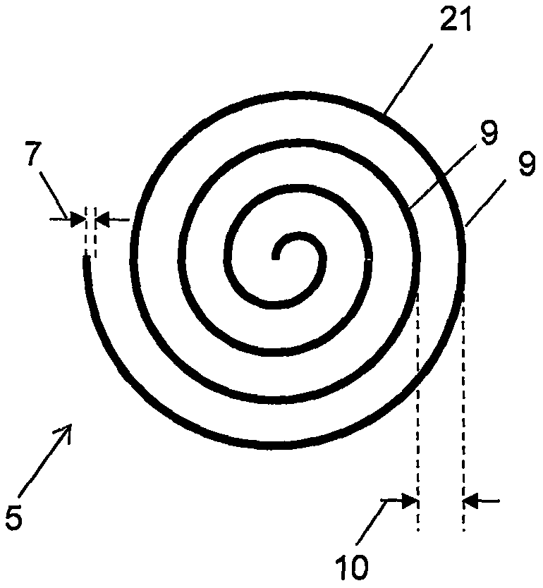
[0061] Figure 15 Shown is a cross-section of an artistically processed weld 150 formed between copper having a thickness 151 of 100 μm and aluminum having a thickness 152 of 400 μm. Weld seam 150 is spiral type, as figure 2 As shown, the first spacing 10 between the helical arms is 50 μm and the diameter 4 is 1 mm. The width 74 of the hole 71 is approximately 5 μm to 20 μm. The weld seam is formed using multiple pulses from the laser 61 overlapping each other on the first material 1 with an area of ​​95%-98%. The laser 61 cuts the first material 1 copper and the second material 2 (aluminum) flows into the hole 71 . At least a portion of the first material 1 is impregnated into the second material 2 , as seen in the region 121 comprising the first material 1 . The region 121 extends approximately 300 μm-400 μm into the second material 2 . Voids 122 also appear. A triangular-like heat-affected zone 155 , shown in dashed lines, appears below the aperture 71 . Only one he...

example 2

[0066] Figure 17 A cross-section of a weld 170 formed between a first material 1 copper and a second material 2 brass is shown. Weld 170 can also be formed as Figure 13The quasi-spiral pattern of the weld shown. Surprisingly, the brass has flowed into the copper material, forming a weld 170 with very little intermetallic mixing. The weld 170 is substantially non-uniform. (missing sentence) Copper and brass flow but do not mix together to form a new homogeneous material phase. The material phases of copper and brass are largely unmixed, and both copper and brass are primary material phases. Especially surprising is that brass is an alloy of copper and zinc. Inside the second material 2 there is some first material 1 . These are also voids 122 . The final joint formed by weld 170 has good shear strength.


PUM

PropertyMeasurementUnit
widthaaaaaaaaaa
reflectanceaaaaaaaaaa

Abstract

Provided is a weld (3) between a first material (1) and a second material (2), the first material (1) being a first metallic material, and the second material (2) being a second metallic material, the weld (3) has a width (4) between 0.5mm and 7mm, the weld (3) comprises at least one microweld (8), the microweld (8) forms a welding pattern (5) defined parallel to a surface (6) of the first material (1), and the microweld (8) has a characteristic feature size (7) of between 20mum and 400mum.

Description

technical field [0001] The invention relates to a laser welding seam. Laser welds can join one or more reflective materials. Laser welded seams have low ohmic resistance, high shear strength and high peel strength. The invention also relates to an article comprising a laser weld. Background technique [0002] Laser welds in workpieces that include one or more reflective metals, such as gold, copper, aluminum, platinum, and silver, are often unreliable and weak. Laser welds in articles comprising dissimilar materials are often brittle and undesirable in nature. [0003] There is a need for a weld between bright and / or dissimilar metals and alloys that does not have reliability issues, and it is an object of the present invention to provide such a weld. Contents of the invention [0004] Therefore, in one non-limiting embodiment of the present invention, a weld between a first material and a second material is provided, the first material is a first metallic material, an...

Claims


Application Information

Patent Timeline
Patent Type & Authority Applications(China)
IPC IPC(8): B23K26/24B23K33/00
CPCB23K26/24B23K26/0622B23K26/21B23K26/08B23K26/22B23K26/32B23K26/0006B23K26/10B23K26/323B23K26/082B23K26/244B23K26/0608B23K26/355F16B5/08
Inventor D·A·卡波斯塔尼奥J·T·加布笛尔M·P·瓦纳姆P·M·哈里森S·R·诺曼A·P·罗索斯基T·墨菲
Owner SPI LASERS UK
Why Eureka
Try Eureka