
Glass cutter box

A glass cutting and cutting knife technology, which is used in glass cutting devices, glass production, glass manufacturing equipment and other directions, can solve the problems of poor cutting accuracy, poor stability, and high scrap rate of raw materials in medium control, so as to improve cutting accuracy and reduce production costs. , the effect of reducing the scrap rate

Active Publication Date: 2016-08-17
ANHUI ZHICHENG NC TECH CO LTD
View PDF5 Cites 5 Cited by
  • Summary
  • Abstract
  • Description
  • Claims
  • Application Information

AI Technical Summary

Problems solved by technology

Currently used glass cutting equipment has problems such as poor control cutting accuracy, poor stability, unstable cutting quality, and high scrap rate of raw materials. finishing needs

Method used


Image

  • Glass cutter box

Examples


Embodiment Construction

[0015] In order to make the object, technical solution and advantages of the present invention clearer, the present invention will be further described in detail below in conjunction with the accompanying drawings and embodiments. It should be understood that the specific embodiments described here are only used to explain the present invention, not to limit the present invention.

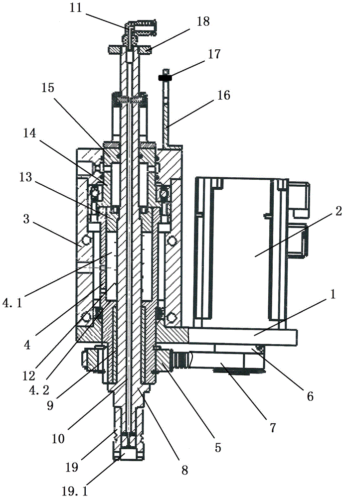
[0016] Such as figure 1 As shown, a glass cutting knife box provided by the present invention includes a support plate 1 on which a motor 2 and a knife box 3 are installed. The knife box 3 is provided with a cavity that is open up and down. The lower side of the knife box 3 is sealed and installed on the support plate 1, and the upper opening is sealed with an end cover 15 with a central through hole.

[0017] In the said knife box 3, a rotary cylinder 4 is connected through bearing rotation fit, and said rotary cylinder 4 is provided with a stepped through hole 4.1, and the aperture on the upper ...


PUM

PropertyMeasurementUnit
thicknessaaaaaaaaaa

Abstract

The invention discloses a glass cutter box which comprises a support plate, wherein a motor and a cutter box are mounted on the support plate; a rotating cylinder is arranged inside the cutter box; a driven wheel is connected with the rotating cylinder in a sleeving manner; the motor is connected with a driving wheel; the driving wheel is connected with the driven wheel through a transmission belt; a cutter rod is mounted inside the rotating cylinder; a return spring is connected with the cutter rod in a sleeving manner; a piston is connected in match inside a step through hole in the upper side of the rotating cylinder; the piston is fixed on the cutter rod in a sleeving manner; a cutter is fixedly connected at the lower end of the cutter rod; a first oil hole is formed inside the cutter rod; a second oil hole which is communicated with the first oil hole is formed inside the cutter; a rotating connector is connected to the upper end of the cutter rod; the rotating connector is communicated with the first oil hole; a pneumatic sleeve is further connected with the cutter rod inside the cutter box in a sleeving manner; the pneumatic sleeve is correspondingly matched with the piston; and a proportional valve is connected with the pneumatic sleeve. The glass cutter box has the advantages that glass of which the thickness is within 2-25mm can be cut, the cutting precision, production efficiency and product quality of ultra-thin glass can be improved, the rejection rate of a raw material can be reduced, and the production cost can be lowered.

Description

technical field [0001] The invention relates to the technical field of photoelectric glass cutting, in particular to a glass cutting knife box. Background technique [0002] Glass cutting mainly refers to cutting large plates of optical glass into different specifications according to requirements, and the cut glass includes various thicknesses. Currently used glass cutting equipment has problems such as poor control cutting accuracy, poor stability, unstable cutting quality, and high scrap rate of raw materials. Finishing needs. Contents of the invention [0003] The object of the present invention is to propose a glass cutting knife box in order to solve the shortcomings in the prior art. [0004] In order to achieve the above object, the present invention adopts the following technical solutions: [0005] A glass cutting knife box, characterized in that it includes a support plate, on which a motor and a knife box are installed, and a rotating drum is arranged in the...

Claims


Application Information

Patent Timeline
Patent Type & Authority Applications(China)
IPC IPC(8): C03B33/02
CPCY02P40/57C03B33/02
Inventor 任明金
Owner ANHUI ZHICHENG NC TECH CO LTD
Learn More