An optical fiber wire-drawing process

A wire drawing and optical fiber technology, applied in the field of optical fiber production, can solve the problems of difficulty in guaranteeing the temperature of coating material, high labor intensity of personnel, high risk of operation and error-prone, etc., and achieve the advantages of convenient unified monitoring, reduced labor intensity, and less labor intensity Effect

Active Publication Date: 2016-08-17
HANGZHOU FUTONG COMM TECH CO LTD
View PDF5 Cites 7 Cited by
  • Summary
  • Abstract
  • Description
  • Claims
  • Application Information

AI Technical Summary

Problems solved by technology

[0004] The invention provides an optical fiber drawing process, which solves the defects of the existing optical fiber drawing process

Method used


Image

  • An optical fiber wire-drawing process
  • An optical fiber wire-drawing process
  • An optical fiber wire-drawing process

Examples


Example Embodiment

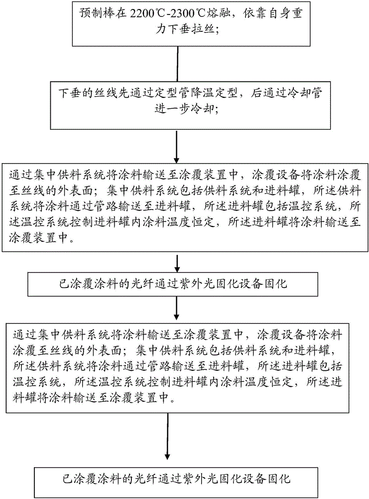
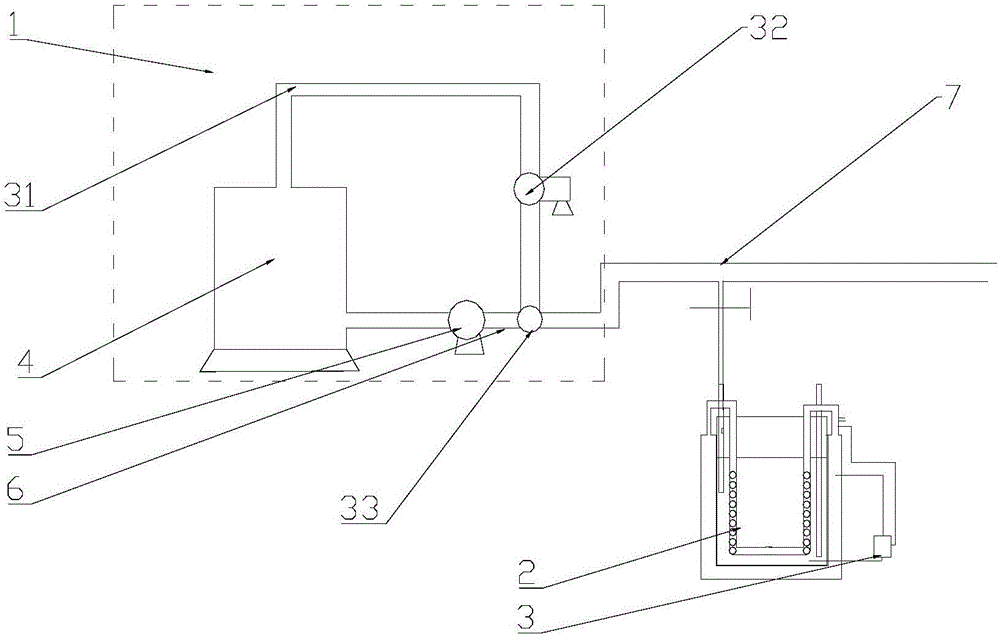
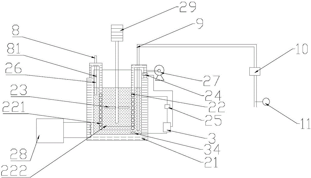
[0038] Embodiment: The embodiment of the present invention discloses a centralized feeding system (see attached figure 2 , 3 , 4), which can be applied to the above steps 3) and 5), the centralized feeding system includes a feeding system 1 and a feeding tank 2. The feeding system transports the paint 1 to the feeding through the pipeline Tank 2. The feed tank 2 includes a temperature control system 3 that controls the temperature of the paint in the feed tank 2 to be constant, and the feed tank 2 delivers the paint to the coating device. The present invention uses a centralized feeding system to uniformly supply and transport the paint, reduces the labor intensity of personnel, and ensures the continuity of production. At the same time, the temperature control system is used to ensure the constant temperature of the paint in the feeding tank and the paint entering the coating device The viscosity is appropriate.

[0039] The supply system 1 includes a storage tank 4, one side o...


PUM


Abstract

An optical fiber wire-drawing process is disclosed. The process includes 1) a melting and wire drawing step, 2) a sizing and cooling step, 3) a first coating step, 4) a first curing step, 5) a second coating step, and 6) a second curing step. The step 3) and the step 5) adopt a same central material supplying system. The central material supplying system comprises a material supplying system and a feeding tank. The material supplying system conveys coating to the feeding tank through a pipeline. The feeding tank comprises a temperature control system. The temperature control system controls the temperature of the coating in the feeding tank to be constant. The feeding tank conveys the coating to a coating device. The central material supplying system is adopted to supply and convey the coating in a unified manner, thus reducing labor intensity of workers and ensuring continuity of production. In addition, the temperature control system is utilized to ensure that the temperature of the coating in the feeding tank is constant, thus ensuring that viscosity of the coating fed into the coating device is proper.

Description

technical field [0001] The invention relates to the field of optical fiber production, in particular to an optical fiber drawing process. Background technique [0002] Optical fiber, short for optical fiber, is a fiber made of glass or plastic that acts as a means of light transmission. The optical fiber is composed of two layers of glass with different refractive indices. The inner layer is the optical core with a diameter of several microns to tens of microns, and the outer layer has a diameter of 0.1 to 0.2 mm. Generally, the refractive index of the inner core glass is 1% larger than that of the outer glass. According to the principle of refraction and total reflection of light, when the angle at which the light hits the interface between the inner core and the outer layer is greater than the critical angle for total reflection, the light cannot pass through the interface and is fully reflected. There are many types of optical fibers, and the required functions and perf...

Claims


Application Information

Patent Timeline
IPC IPC(8): C03B37/025C03C25/12C03C25/62
CPCC03B37/025C03C25/1065C03C25/12C03C25/48C03C25/6226Y02P40/57
Inventor 杨喜海胡涛涛何建儿
Owner HANGZHOU FUTONG COMM TECH CO LTD
Why Eureka
Try Eureka