
Multibeam sonar probe boat head mounting device and use method thereof

A multi-beam and sonar technology, which is applied to ship components, ship construction, transportation and packaging, etc., can solve problems such as processing difficulties, increasing labor workload, and affecting the detection performance of multi-beam sonar probes, so as to ensure versatility and reduce labor Effects of strength, overcoming safety and operational sustainability

Inactive Publication Date: 2016-08-17
SECOND INST OF OCEANOGRAPHY MNR
View PDF6 Cites 17 Cited by
  • Summary
  • Abstract
  • Description
  • Claims
  • Application Information

AI Technical Summary

Problems solved by technology

However, the installation on the side of the ship also has its own limitations. For example, the installation position is often close to the stern of the ship, which is greatly affected by the wake flow, which affects the detection performance of the multi-beam sonar probe; the device structure is more complicated and the processing is more difficult; the installation and recycling of equipment require more completed by people, increasing the workload of labor

Method used


Image

  • Multibeam sonar probe boat head mounting device and use method thereof
  • Multibeam sonar probe boat head mounting device and use method thereof
  • Multibeam sonar probe boat head mounting device and use method thereof

Examples


Embodiment 1

[0033] Embodiment 1 Multi-beam sonar probe bow installation device

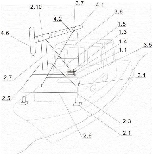
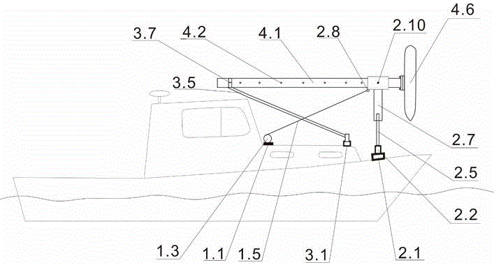
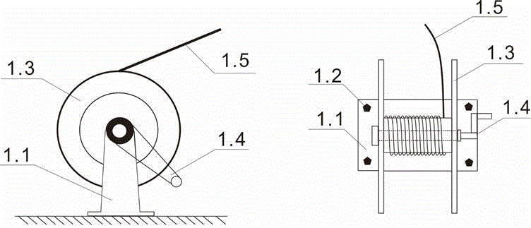
[0034] Refer to attached figure 1 To attach Figure 8 , a multi-beam sonar probe bow-mounted device, including elevators (such as image 3 ), the herringbone bracket (such as Figure 5 shown), A-shaped brackets (such as Figure 6 shown) and transducer mounting brackets (such as Figure 7 ); all components are recommended to be constructed of seawater resistant materials with an anti-fouling coating.

[0035] See attached image 3 , the lifter includes a lifter base 1.1, a lifter base bolt 1.2, a steel cable reel 1.3, a rocker arm 1.4 and a steel cable 1.5; the lifter base 1.1 is fixedly installed on the hull using the lifter base bolt 1.2, which is convenient for the position of the device Adjustment; the rocker arm 1.4 and the steel cable reel 1.3 are fixedly welded, and placed on the support of the elevator base 1.1; the steel cable 1.5 is wound in the steel cable drum 1.3, and the rotation of the roc...

Embodiment 2

[0039] Embodiment 2 Deployment of multi-beam sonar probes

[0040] See attached Figure 9 As shown in step 1 in , mount the multi-beam sonar probe to be mounted on the installation slot in the fairing 4.6 and fix it; the hollow lifting rod 4.1 passes through the probe cable and connects to the dry end of the multi-beam sonar system host; see attached Figure 9 As shown in step 2, remove the hoop 3.7 on the A-shaped bracket, turn the rocker arm 1.4 on the lifter clockwise, loosen the steel cable 1.5 slowly, and push the upper part of the herringbone bracket with the pin 2.4 as the The axis slowly reverses to the bow in a clockwise direction, and at the same time drives the multi-beam sonar probe at the lower end of the transducer mounting bracket to slowly approach the sea surface; see attached Figure 9 As shown in steps 3 and 4, when the transducer mounting bracket is 90° to the sea surface, loosen the positioning bolt 2.10, adjust the depth of the lifting rod 4.1 up and do...


PUM


Abstract

The invention discloses a multibeam sonar probe boat head mounting device and a use method thereof. The multibeam sonar probe boat head mounting device is mainly composed of a riser, an A-shaped bracket, a reversed-Y-shaped bracket and an energy transducer mounting bracket. The riser, the A-shaped bracket and the reversed-Y-shaped bracket are successively fixed at a boat head position through corresponding bases. The energy transducer mounting bracket passes through a T-shaped sleeve at the upper part of the reversed-Y-shaped bracket and is fixed by a positioning bolt. An upper flange is welded on the bottom of the energy transducer mounting bracket and is fixed to a lower flange at top of a radome through a flange mounting bolt. The wire rope of the riser is connected with the wire rope on the A-shaped bracket. A wire rope reel is driven through shaking a rocking arm, thereby finishing folding and unfolding of the multibeam sonar probe boat head mounting device. The multibeam sonar probe boat head mounting device and the use method thereof have advantages of convenient operation, low cost, effective insurance for high precision of acquired data by a multibeam detecting instrument, and effective insurance for high safety of the instrument. A design of adjustable water entering depth of the energy transducer is utilized. Experiments represent a fact that the multibeam sonar probe boat head mounting device can be used on small-size boats with different drafts. High versatility of the multibeam sonar probe boat head mounting device is ensured. Furthermore the multibeam sonar probe boat head mounting device can be widely used in marine surveying and marine engineering.

Description

technical field [0001] The invention belongs to the technical field of marine survey and seabed detection, and specifically refers to a multi-beam sonar probe bow installation device and method. Background technique [0002] Marine survey and seabed detection are the basis of ocean management, engineering design, sea area delimitation, resource development, national defense security and marine scientific research. Ship-borne survey is the most basic way of marine survey, which can provide a large amount of survey data for marine scientific research and engineering. The correct installation of marine survey instruments is a strong guarantee for obtaining effective survey data. As an important content of marine hydrographic survey, seabed topography and geomorphology survey is the most basic marine survey work. In order to reveal useful information such as the topography and substrate type of the seabed, high-resolution multi-beam topography and geomorphology detection is on...

Claims


Application Information

Patent Timeline
IPC IPC(8): G01S7/52B63B17/00
CPCB63B17/00B63B2017/0054G01S7/521
Inventor 赵荻能吴自银李家彪周洁琼梁裕扬尚继宏李守军周勐佳陈佳兵马永张田升
Owner SECOND INST OF OCEANOGRAPHY MNR
Learn More