Quantum dot light source device, backlight module and liquid crystal display device

A backlight module, quantum dot technology, applied in semiconductor devices, optics, instruments, etc., can solve the problem of inconsistent color of outgoing light

Inactive Publication Date: 2016-08-17
HISENSE VISUAL TECH CO LTD
View PDF4 Cites 32 Cited by
  • Summary
  • Abstract
  • Description
  • Claims
  • Application Information

AI Technical Summary

Problems solved by technology

[0006] The present invention provides a quantum dot light source device, a backlight module and a liquid crystal display device, so as to overcome the problem of inconsistency in the color of emitted light from different positions of the quantum dot light source device in the related art

Method used


Image

  • Quantum dot light source device, backlight module and liquid crystal display device
  • Quantum dot light source device, backlight module and liquid crystal display device
  • Quantum dot light source device, backlight module and liquid crystal display device

Examples


Embodiment 1

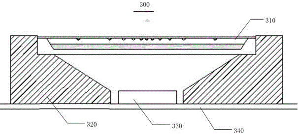
[0040] image 3 A schematic structural diagram of a quantum dot light source device is provided for the implementation of the present invention; Figure 4 It is a schematic structural diagram of the quantum dot encapsulation part in Embodiment 1 of the present invention; Figure 5 It is a structural schematic diagram of the dot layout of the upper packaging substrate in Embodiment 1 of the present invention.

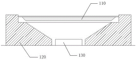
[0041] Such as image 3 As shown, a quantum dot light source device 300 can be used as a backlight in direct-type backlight modules and side-type backlight modules, and can be used as a lighting source, including:

[0042]The PCB printed circuit board 340 provides a power circuit for the quantum dot light source device 300 .

[0043] The LED light-emitting chip 330 is arranged on the PCB printed circuit board 340 to generate excitation light.

[0044] The packaging bracket 320 , the bottom end of the packaging bracket 320 is arranged on the PCB printed circuit board ...

Embodiment 2

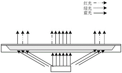
[0060] Figure 6 A schematic structural diagram of another quantum dot light source device is provided for the second implementation of the present invention; Figure 7 It is a schematic structural diagram of the quantum dot encapsulation part in Embodiment 2 of the present invention; Figure 8 It is a schematic diagram of the light transmission characteristics of the dichroic light transmission layer in Example 2 of the present invention; Figure 9 It is a schematic diagram of the optical characteristics of the quantum dot light source device in the second embodiment of the present invention.

[0061] The difference between the second embodiment and the first embodiment is that in the second embodiment, on the basis of the first embodiment, a dichroic light-transmitting layer is provided on the lower substrate of the quantum dot packaging part, which can transmit the wavelength light of the excitation light source. , and reflect the wavelength light of the excited light sou...

Embodiment 3

[0073] The third embodiment provides a direct type backlight module, which uses a quantum dot light source device to provide a light source.

[0074] Figure 10 It is a structural schematic diagram of a direct type backlight module in the third embodiment, as Figure 10 As shown, the direct type backlight module 10 includes:

[0075] The fixing part 12 is used for assembling the direct type backlight module 10 together, such as connecting parts such as a backplane and a plastic frame.

[0076] The quantum dot light source device 11 is arranged on the fixing part 12 and is located directly below the direct type backlight module 10, and the quantum dot light source device 11 is any one of the quantum dot light source devices in the first embodiment and the second embodiment.

[0077] The homogenizing optical component 13 is used for homogenizing the light source provided by the quantum dot light source device 11 .


PUM


Abstract

The invention provides a quantum dot light source device, a backlight module and a liquid crystal display device. A quantum dot packaging part comprises an upper base plate, a lower baste plate and a quantum dot material layer, wherein the quantum dot material layer is packaged by the upper base plate and the lower baste plate, and lattice points are arranged on the upper base plate, so that the reflectivity on the center position of the upper base plate is more than that on the peripheral edge position, and the problem of inconsistent colors of emitting light on different positions of the quantum dot light source device in the prior art is solved.

Description

technical field [0001] The invention relates to the field of display technology, in particular to a quantum dot light source device, a backlight module and a liquid crystal display device. Background technique [0002] A liquid crystal display device is composed of a liquid crystal panel, a mechanism frame, optical components, and some circuit boards. Since the liquid crystal itself does not emit light, some backlight sources need to be configured to display the picture. Wherein, the backlight module is used to provide a backlight with uniform brightness and distribution for the liquid crystal display device, so that the liquid crystal display device can display images normally. [0003] The backlight module can be divided into side-type backlight module and direct-type backlight module according to the light incident position of the light source. The back array is placed, and the emitted light passes through the optical film such as the light guide plate and the enhanceme...

Claims


Application Information

Patent Timeline
Patent Type & Authority Applications(China)
IPC IPC(8): G02F1/13357
CPCG02F1/133603G02F1/133605G02F1/133611G02F1/133614G02F2202/36H01L33/502H01L33/505H01L33/58
Inventor 李富琳
Owner HISENSE VISUAL TECH CO LTD
Why Eureka
Try Eureka