
High-speed serial bus storage device provided with multiple high-speed interfaces

A high-speed serial bus and storage device technology, applied in the input/output process of data processing, instruments, electrical digital data processing, etc., can solve the problems of increased power consumption of disk arrays, slow read and write speeds, and low stability , to achieve the effect of guaranteeing reliability, improving reading and writing speed, and rich resources

Pending Publication Date: 2016-08-17
北京中科海讯数字科技股份有限公司
View PDF0 Cites 6 Cited by
  • Summary
  • Abstract
  • Description
  • Claims
  • Application Information

AI Technical Summary

Problems solved by technology

[0003] At present, most data storage systems are traditional disk array RAID. Since the invention of disk array RAID, its storage capacity and reliability have been continuously improved. However, this disk array RAID itself has some disadvantages: slow read and write speed : The traditional disk array RAID adopts the high-speed rotating head of the disk as the data reading method, so the addressing time is long and the reading and writing speed is slow; the stability is low: the mechanical structure of the traditional disk array RAID causes the wear of the magnetic head and the deformation of the cantilever, and When the disk array is subjected to vibration, its working performance will be unstable, and it is not applicable under harsh environmental conditions: high power consumption: the mechanical rotation of the disk and the radial movement of the magnetic head in the traditional disk array RAID will be to a large extent The power consumption of the disk array increases
However, since NANDFLASH chips do not have a unified interface specification standard, issues such as ECC verification, bad block management, and load balancing must be considered when using them. To achieve stable and reliable data storage, there are many disadvantages in terms of complexity and resource consumption.

Method used


Image

  • High-speed serial bus storage device provided with multiple high-speed interfaces
  • High-speed serial bus storage device provided with multiple high-speed interfaces

Examples


Embodiment Construction

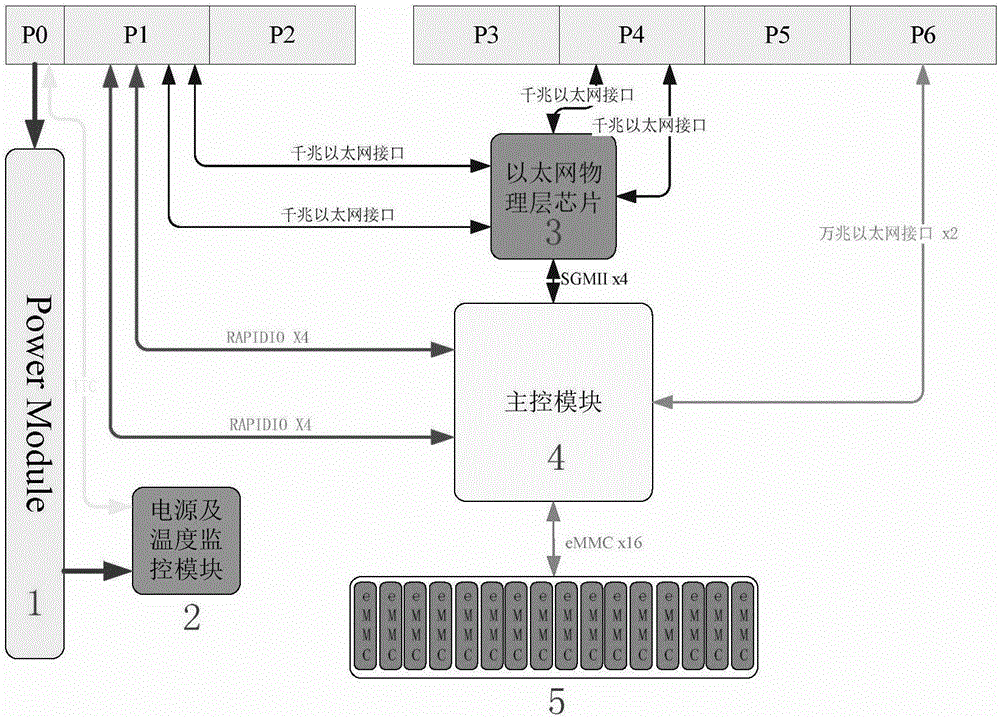
[0023] Preferably, the main control module 4 of the present invention adopts an FPGA chip, and the storage unit adopts an EMMC chip, and there are four groups of four chips in total.

[0024] According to the usage of different network interfaces, the usage efficiency is improved. Preferably, the main control module leads two RAPIDIO interfaces, two 10 Gigabit Ethernet interfaces, and 4 Gigabit Ethernet interfaces to the outside of the board.

[0025] In order to better monitor the working conditions of the power supply, the power supply and temperature monitoring module obtains power supply data through the combination of precision resistors and INA230, and obtains temperature data through the TMP100 chip. The power supply and temperature data communicate with the MCU through the IIC bus, and the summarized monitoring The data is sent to the host computer through IIC or serial port.


PUM


Abstract

The invention discloses a high-speed serial bus storage device provided with multiple high-speed interfaces. The high-speed serial bus storage device is designed to solve the problem that data acquired at a high speed cannot be stored timely, a 10-gigabit Ethernet, a gigabit Ethernet and an RAPIDIO interface are provided in the design, and accordingly, interface butt joint with other data acquisition boards is facilitated. By means of the advantage of rich resources of FPGA (field programmable gate array) chip pins, read-write operation is performed on 16 eMMC (embedded multimedia card) chips in parallel, and the read-write speed of a whole board is increased. The eMMC chips are selected as the storage chips, and the reliability of data of the whole board is guaranteed by means of the high-reliability characteristic of the eMMC chips. The eMMC chips follow uniform interface standards, and upgrading of the capacity and the speed of storage equipment can be easily completed under the condition that other hardware is not changed with the development of an eMMC technology.

Description

technical field [0001] The invention belongs to the technical field of digital signal processing, in particular to realizing a high-speed memory board based on an eMMC memory chip by using FPGA. Background technique [0002] With the rapid development of information science and technology, in the field of modern real-time signal processing, in order to obtain more accurate and effective information, it is necessary to obtain a large amount of data for processing, and the former high-speed data acquisition system has been used in radar, sonar, image processing, voice It is widely used in identification, communication, transient signal testing and other fields. A large amount of data is generated when the sensor array works, and the parallelism of the data is very real-time, so high-speed storage devices are needed to store the data. [0003] At present, most data storage systems are traditional disk array RAID. Since the invention of disk array RAID, its storage capacity and...

Claims


Application Information

Patent Timeline
IPC IPC(8): G06F13/40G06F13/42G06F3/06
CPCG06F3/0655G06F13/4068G06F13/4282G06F2213/0008
Inventor 张华英
Owner 北京中科海讯数字科技股份有限公司
Features
  • Generate Ideas
  • Intellectual Property
  • Life Sciences
  • Materials
  • Tech Scout
  • Unparalleled Data Quality
  • Higher Quality Content
  • 60% Fewer Hallucinations
Learn More