A slurry-driven stirring flotation equipment with self-adjusting slurry and self-defoaming functions

A self-adjusting slurry and stirring technology, applied in flotation, solid separation, etc., can solve the problems affecting the flotation effect, excessive turbulence in the flow field, and particle shedding, so as to improve the spray impact force, generate stability, and improve The effect of spawn rate

Active Publication Date: 2017-11-07
ANHUI UNIV OF SCI & TECH
View PDF2 Cites 1 Cited by
  • Summary
  • Abstract
  • Description
  • Claims
  • Application Information

AI Technical Summary

Problems solved by technology

Since the non-mechanical stirring flotation machine has no stirring mechanism, the pump is used to provide energy for the pulp, and the jet flow and collision of the pulp are dispersed to absorb enough air. The disadvantage is that it needs a matching pump and consumes a lot of energy.
In addition, since the non-mechanical agitation flotation machine needs to ensure sufficient ore flow and suction capacity, the flow field in the flotation tank is often excessively turbulent, causing the mineralized particles to fall off during the flotation process, thereby affecting the flotation effect

Method used


Image

  • A slurry-driven stirring flotation equipment with self-adjusting slurry and self-defoaming functions
  • A slurry-driven stirring flotation equipment with self-adjusting slurry and self-defoaming functions
  • A slurry-driven stirring flotation equipment with self-adjusting slurry and self-defoaming functions

Examples


Embodiment Construction

[0048] For ease of understanding, combined here Figure 1-7 , the specific embodiments of the present invention are further described as follows:

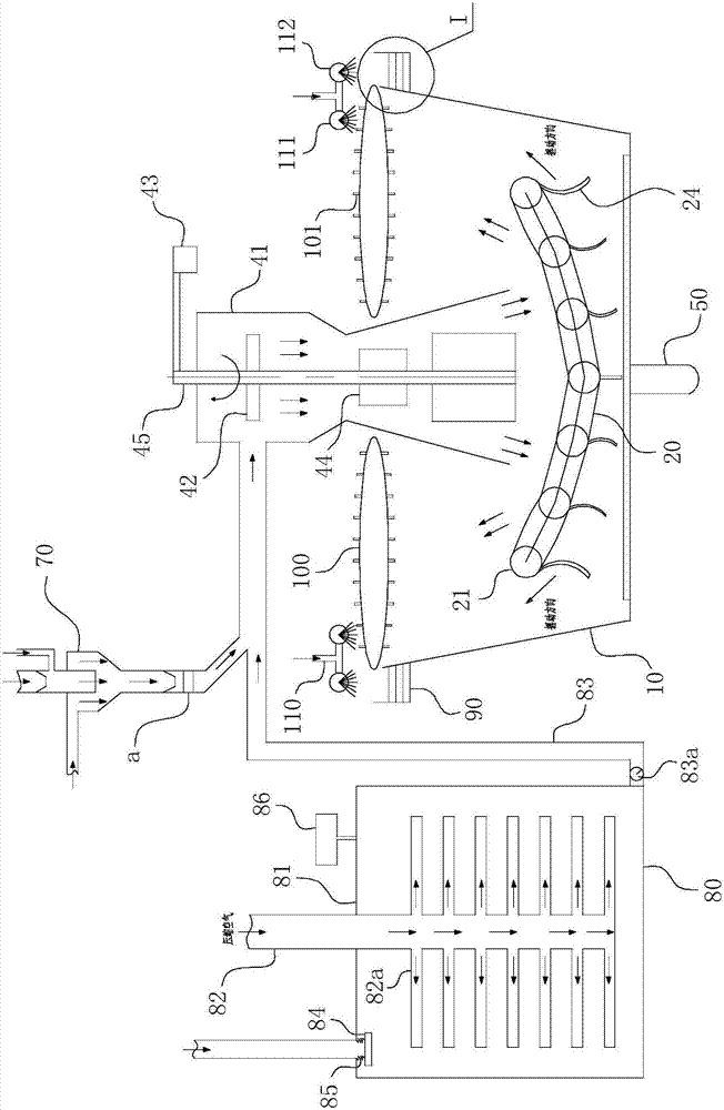
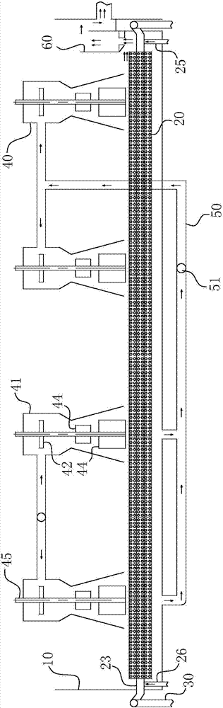
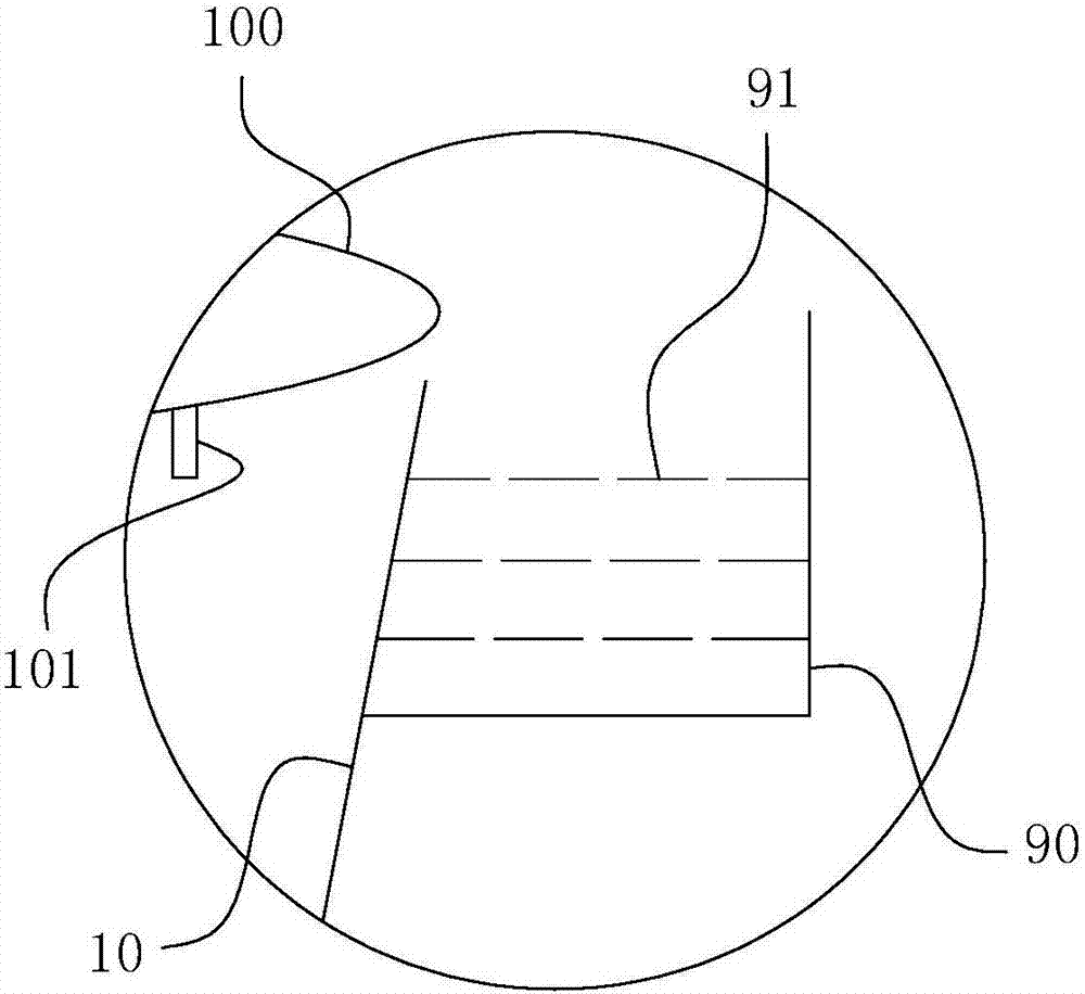
[0049] The specific components of the present invention are divided into several major modules, including: flotation cell 10, flotation feeding pressurized buffer tank 80, double sleeve jet assembly 70, driving stirring mechanism 40, microbubble generating bed 20, circulation type Bubble scraping assembly 100, clean water spraying assembly 110 and tailings box. Describe them one by one below:

[0050] 1. Flotation feeding pressure buffer tank

[0051] Its structure is as figure 1 As shown, a sealed cylindrical tank body 81 is included, and a compressed air pipe 82 is coaxially arranged vertically in the tank body 81 . The air inlet at the top of the compressed air pipe 82 is connected to an external air source, while the air outlet section at the bottom is distributed in a fork shape or in a layered branch-like arrangement with...


PUM


Abstract

The invention relates to the field of coal slurry pulp conditioning flotation treatment, in particular to pulp drive agitating type flotation equipment with self pulp conditioning and self defoaming functions. The pulp drive agitating type flotation equipment at least comprises a flotation tank and a drive agitating mechanism; the feeding end of the drive agitating mechanism is of a fork structure, one inlet end of the drive agitating mechanism is communicated with a double-sleeve jet flow assembly used for jet flow of flotation reagents, and the other inlet end is communicated with a flotation feeding pressure buffer tank; bubble overflow grooves are formed in the two side tank walls in the length direction of the flotation tank, and are formed in the outer side wall of the tank wall of the flotation tank, and an overflow wall is formed through the outer side wall of the tank wall of the flotation tank; at least one layer of defoaming screen plate for defoaming is horizontally arranged in a groove body of each bubble overflow groove; and the equipment further comprises a defoaming spraying head and a tailing box. The equipment has the beneficial effects that bubble mineralization is easier, a foam layer is more stable, and the defoaming process is more rapid; the concentrate taste can be effectively improved, and meanwhile great convenience is provided for transportation of subsequently-transported flotation foam.

Description

technical field [0001] The invention relates to the field of coal slurry flotation treatment, in particular to a slurry-driven stirring flotation device with self-slurry and self-defoaming functions. Background technique [0002] Flotation is the most important interface separation method, usually used for the separation of -0.5mm coal slime, and it is the only effective separation method for -0.1mm coal slime. There are many types of flotation machines, and the differences are mainly reflected in the inflation method and the structure of the inflation stirring device. At present, the most widely used classification method is to divide flotation machines into two categories: mechanical agitation type and non-mechanical agitation type according to the different aeration and agitation methods. The mechanical agitation flotation machine can refer to the Chinese patent announcement number "CN201711220U" named "mechanical agitation flotation machine", which uses the stirring of ...

Claims


Application Information

Patent Timeline
Patent Type & Authority Patents(China)
IPC IPC(8): B03D1/22
CPCB03D1/22
Inventor 朱金波周伟白雪杰韩有理费之奎王超张雪菲
Owner ANHUI UNIV OF SCI & TECH
Why Eureka
Try Eureka