A magnetic-gas composite fluid grinding head device

A magnetic-gas composite and grinding head technology, which is applied in the direction of grinding machines, optical surface grinding machines, grinding/polishing equipment, etc., can solve the problem that the magnetic fluid is difficult to replace effectively, and achieve easy industrial implementation, improve processing efficiency, improve utilization rate and The effect of recovery

Inactive Publication Date: 2018-01-16
ZHEJIANG UNIVERSITY OF SCIENCE AND TECHNOLOGY
View PDF6 Cites 0 Cited by
  • Summary
  • Abstract
  • Description
  • Claims
  • Application Information

AI Technical Summary

Problems solved by technology

[0005] The purpose of the present invention is to solve the problem that the magnetic fluid is difficult to effectively replace in view of the deficiencies of the prior art, and to provide a magnetic-gas composite fluid grinding head device

Method used


Image

  • A magnetic-gas composite fluid grinding head device
  • A magnetic-gas composite fluid grinding head device
  • A magnetic-gas composite fluid grinding head device

Examples


Embodiment

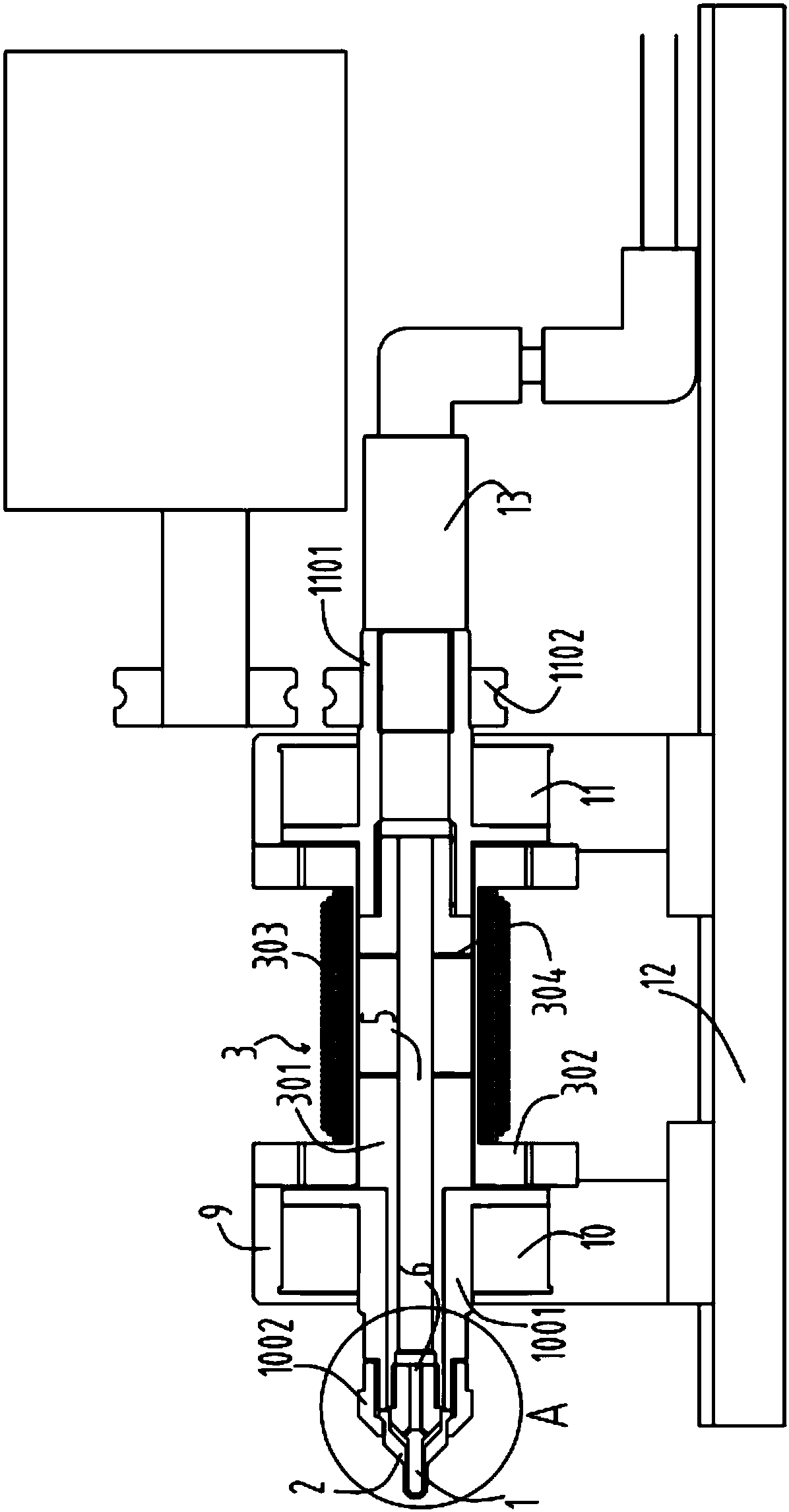
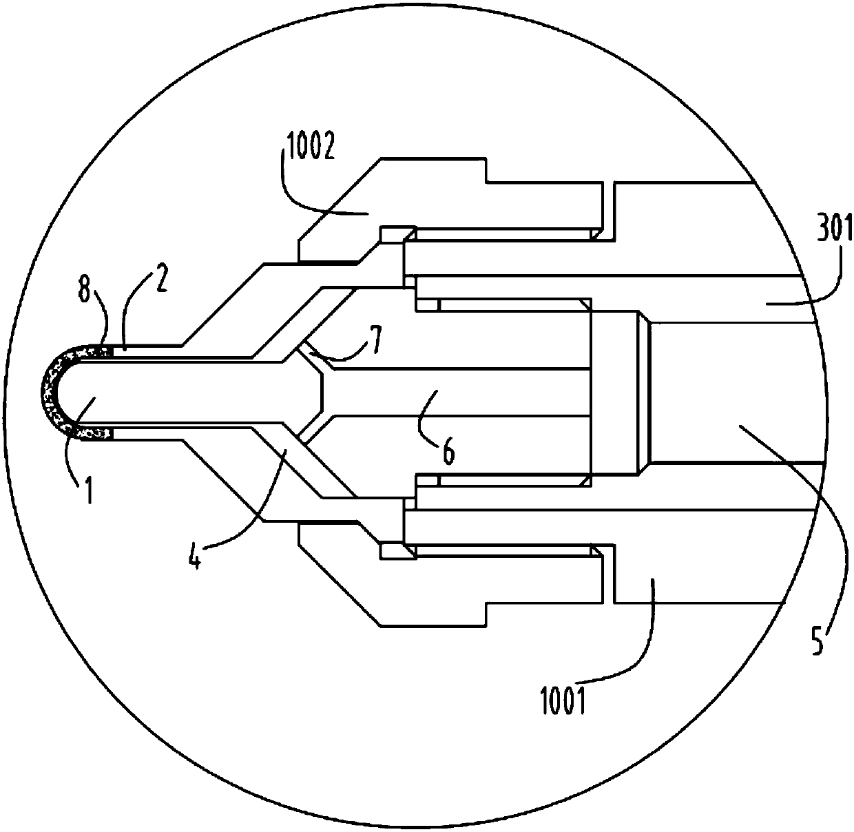
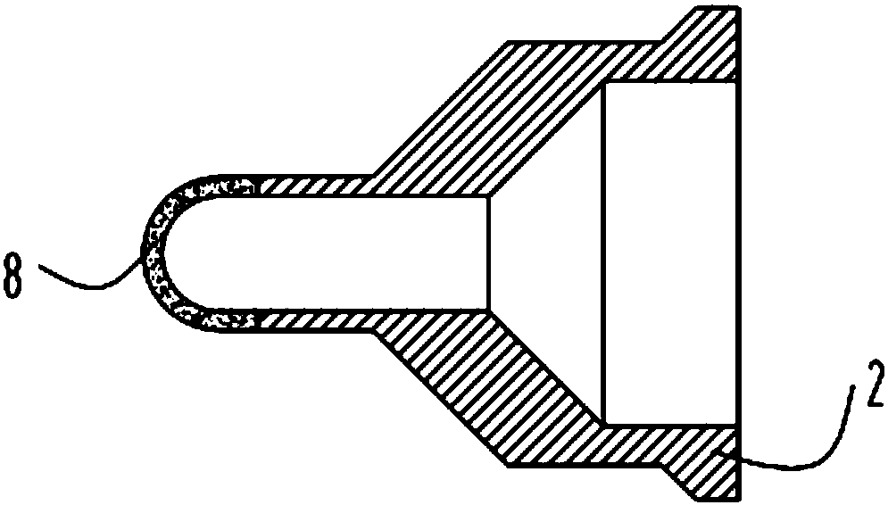
[0033] figure 1 It is a schematic diagram of the magnetic-gas composite fluid grinding head device, figure 2 forfigure 1 Partial enlarged schematic diagram of A, image 3 An enlarged schematic diagram of the air hole grinding head, Figure 4 An enlarged schematic diagram of the magnetic core grinding head, Figure 5 An enlarged schematic diagram of the electromagnet mandrel, Figure 6 Enlarged schematic diagram for bearing positioning sleeve A, Figure 7 Enlarged schematic diagram for bearing positioning sleeve B, Figure 8 Enlarged schematic diagram for the coil insulation sleeve, Figure 9 Zoom in on the schematic for the threaded retainer. Such as figure 1 , figure 2 , image 3 , Figure 4 , Figure 5 , Figure 6 , Figure 7 , Figure 8 and Figure 9 As shown, a magnetic-gas composite fluid grinding head device includes a magnetic core grinding head 1, an air hole grinding head 2 and an excitation device 3. The front end of the magnetic core grinding head 1...


PUM


Abstract

The invention relates to a magnetic-gas compound fluid grinding head device which comprises a magnetic core grinding head (1), a gas hole grinding head (2) and an exciting device (3), wherein a front end of the magnetic core grinding head (1) is located in the gas hole grinding head (2); a gap (4) is formed between the front end of the magnetic core grinding head (1) and the gas hole grinding head (2); a back end of the magnetic core grinding head (1) is fixedly connected with the exciting device (3); the gas hole grinding head (2) and the magnetic core grinding head (1) synchronously rotate; a gas passage (5) is arranged inside the exciting device (3); a cavity (6) is arranged at the back end of the magnetic core grinding head (1); the gas passage (5) is connected with the cavity (6); a through hole (7) is arranged between the cavity (6) in the magnetic core grinding head (1) and the gap (4); gas holes (8) are arranged in a surface of the gas hole grinding head (2). The magnetic-gas compound fluid grinding head device solves a problem that a magnetic fluid is difficult to effectively replace, and the magnetic-gas compound fluid grinding head device is provided.

Description

technical field [0001] The invention relates to the technical field of ultra-precision machining, in particular to a magnetic-gas composite fluid grinding head device. Background technique [0002] Micro-aspheric optical parts are generally in the range of a few millimeters to tens of millimeters in diameter, and are very important optical parts. In terms of military use, the optical systems of photoelectric instruments such as laser guidance systems, radar ranging systems, aviation and aerospace telescopic camera systems, and infrared thermal imaging engineering are widely used in various optical materials such as micro-aperture aspheric mirrors. And it is more widely used in civilian use, such as photoelectric lenses, infrared remote monitoring mirrors, video recorder lenses, laser video disc devices, X-ray lenses for medical diagnosis, indirect ophthalmoscopes, endoscopes, progressive lenses, digital cameras, CCD camera lenses, etc. Products, these require a large number...

Claims


Application Information

Patent Timeline
Patent Type & Authority Patents(China)
IPC IPC(8): B24B1/00B24B13/01B24B13/00
CPCB24B1/005B24B13/00B24B13/01
Inventor 王宇贺剑波杨东凌叶鸿锋
Owner ZHEJIANG UNIVERSITY OF SCIENCE AND TECHNOLOGY
Why Eureka
Try Eureka