Supercharge Your Innovation With Domain-Expert AI Agents!

Flue gas waste heat recovery device capable of changing super conductive tube rapidly

A technology of superconducting heat pipes and flue gas waste heat, which is applied in indirect heat exchangers, lighting and heating equipment, and steam generation methods using heat carriers, etc. Poor effect and other problems, to achieve the effect of convenient disassembly and replacement of heat pipes, small footprint, and fast replacement

Active Publication Date: 2016-08-24
武汉朗涤环保科技工程有限公司
View PDF8 Cites 6 Cited by
  • Summary
  • Abstract
  • Description
  • Claims
  • Application Information

AI Technical Summary

Problems solved by technology

Although liquid spray cooling cools down quickly, the heat energy cannot be utilized, and it will also produce mist with secondary pollution, which is not suitable for the principle of energy saving and consumption reduction
Although waste heat boilers and tube-and-tube heat exchangers can recover waste heat, the waste heat recovery effect is poor, the floor space is large, and it is not suitable for small flue gas occasions, etc.

Method used


Image

  • Flue gas waste heat recovery device capable of changing super conductive tube rapidly
  • Flue gas waste heat recovery device capable of changing super conductive tube rapidly
  • Flue gas waste heat recovery device capable of changing super conductive tube rapidly

Examples


specific Embodiment 1

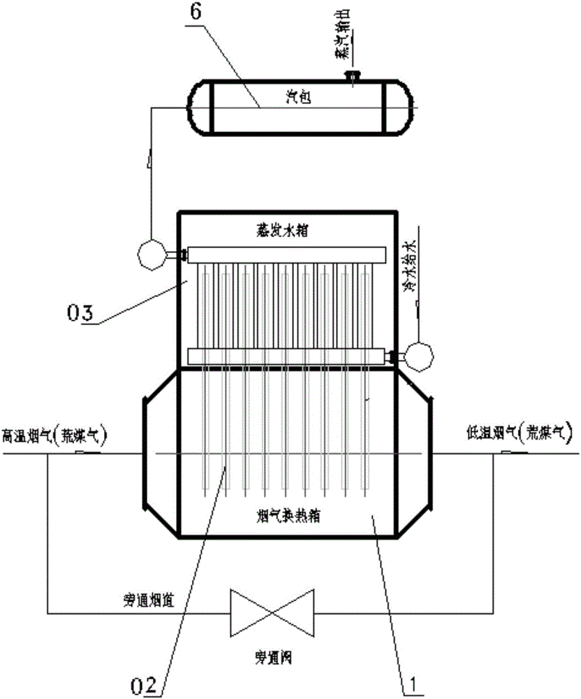
[0021] combined with figure 1 , a flue gas waste heat recovery device for quick replacement of superconducting heat pipes, which includes a flue gas heat exchange box 1, a superconducting heat pipe 02, an evaporation water tank 03 and a steam drum 6; the flue gas heat exchange box 1 is used for waste heat recovery, The lower part of the superconducting heat pipe 02 is installed in the flue gas heat exchange box 1, and the upper part of the superconducting heat pipe 02 is installed in the evaporation water tank 03. The superconducting heat pipe 02 is used to absorb the waste heat of the flue gas heat exchange box and transfer the waste heat to the evaporation water tank 03; the evaporating water tank 03 is installed above the flue gas heat exchange box 1 to absorb the heat energy of the superconducting heat pipe 02, so that the water in the water tank becomes steam; the evaporating water tank 03 is also connected with a steam drum 6 through a pipeline; The bag 6 is used to stor...

specific Embodiment 2

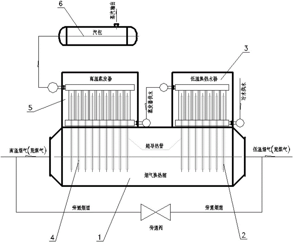
[0022] further combined with figure 2 , a superconducting heat pipe quick replacement flue gas waste heat recovery device, which includes a flue gas heat exchange box 1, a superconducting heat pipe, an evaporation water tank and a steam drum 6; the superconducting heat pipe includes a low-temperature section superconducting heat pipe 2 and a high-temperature section Two parts of superconducting heat pipe 4; described evaporating water tank includes two parts of low temperature water exchange heater 3 and high temperature evaporator 5; described low temperature section superconducting heat pipe 2 communicates with flue gas heat exchange box 1 and low temperature water exchange heater 3, The waste heat of the low-temperature flue gas in the flue gas heat exchange box 1 is introduced into the low-temperature water exchange heater 3; the high-temperature section superconducting heat pipe 4 is connected with the flue gas heat exchange box 1 and the high-temperature evaporator 5, an...


PUM


Abstract

The invention provides a flue gas waste heat recovery device capable of changing a super conductive tube rapidly, wherein the flue gas waste heat recovery device is high in heat conduction speed, high in heat exchange efficiency, small in occupied area and compact in shape, the conductive tube can be changed easily, and the flue gas waste heat recovery device is suitable for waste heat recovery occasions with various glue gas properties. The flue gas waste heat recovery device comprises a flue gas heat exchange tank, the super conductive tube, an evaporation water tank and a steam pocket; the flue gas heat exchange tank is used for recovering waste heat, the lower part of the super conductive tube is installed in the flue gas heat exchange tank, the upper part of the super conductive tube is installed in the evaporation water tank, and the super conductive tube is used for absorbing waste heat of the flue gas heat exchange tank and conveying the waste heat to the evaporation water tank; the evaporation water tank is installed at the upper part of the flue gas heat exchange tank and is used for absorbing the heat energy of the super conductive tube, so that water in the water tank is changed into steam; the evaporation water tank is further connected with the steam pocket through a pipeline; the steam pocket is used for storing steam produced by the evaporation water tank; the evaporation water tank is further connected with a cold water supply pipeline; the fixation mode of the super conductive tube and the evaporation water tank is insertion fixation.

Description

technical field [0001] The invention relates to a waste heat recovery device suitable for various high-temperature flue gases, in particular to a flue gas waste heat recovery device for quick replacement of superconducting heat pipes for recovery and utilization of flue gas waste heat. Background technique [0002] At present, hot flue gas is produced in various industries, especially in metallurgical systems, power plant boilers, domestic boilers, and boilers and kilns in glass, building materials, papermaking, and ceramic industries. High-temperature flue gas is generated, and waste heat energy is greatly wasted. At present, the recovery rate of waste heat in various industries is still very low. To make full use of energy and establish a resource-saving and environment-friendly green enterprise, energy conservation is the direction of development and one of the main ways to reduce energy consumption of enterprises. In order to fully realize the energy saving and consumpti...

Claims


Application Information

Patent Timeline
IPC IPC(8): F28D15/02F22B1/18
CPCF22B1/18F28D15/02
Inventor 周志存唐必烈陈兰洲綦杰
Owner 武汉朗涤环保科技工程有限公司
Features
  • R&D
  • Intellectual Property
  • Life Sciences
  • Materials
  • Tech Scout
  • Unparalleled Data Quality
  • Higher Quality Content
  • 60% Fewer Hallucinations
Learn More