Line filter
A filter and line technology, applied in circuits, inductors, fixed inductors, etc., can solve the problem of weakening the noise removal effect, and achieve the effect of high-precision positioning
- Summary
- Abstract
- Description
- Claims
- Application Information
AI Technical Summary
Problems solved by technology
Method used
Image

Examples
no. 1 Embodiment approach example
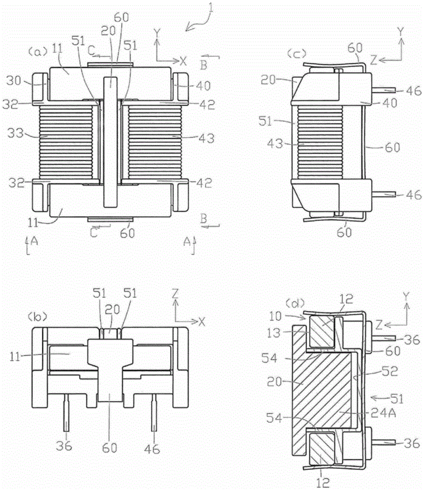
[0091] exist Figure 1 to Figure 7 Among them, the line filter (power supply filter) 1 of this embodiment has a common mode core 10 , a normal mode core 20 , a first bobbin 30 , a second bobbin 40 , a case 50 , and a stopper mechanism 60 .
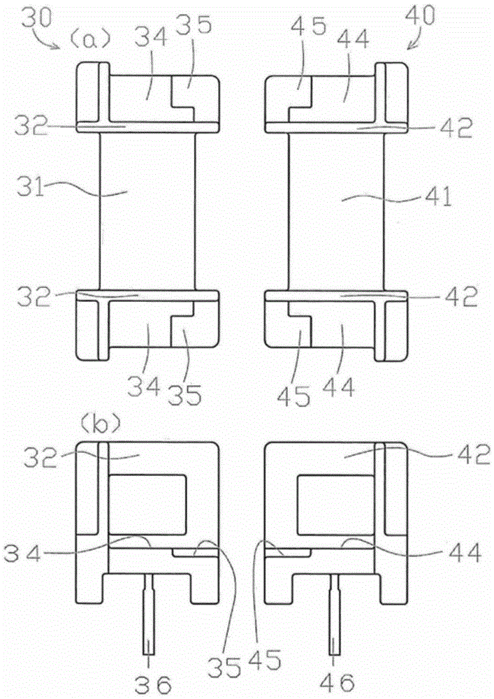
[0092] Such as figure 1 or image 3 As shown, the first bobbin 30 and the second bobbin 40 are two independent bobbins made of non-magnetic thermosetting resin. The first bobbin 30 and the second bobbin 40 have: a first cylindrical trunk part 31 and a second cylindrical trunk part 41; the first flange portion 32 and the second flange portion 42 on both sides; the first coil 33 and the second The coil 43; the first terminal block 34 and the second terminal block 44 provided on both sides in the axial direction (Y direction) of the first cylindrical trunk portion 31 and the second cylindrical trunk portion 41; and fixed to the first terminal block 34 and the I-shaped first terminal 36 and second terminal 46 below the second terminal blo...
no. 2 Embodiment approach example
[0121] next pass Figure 8 or Figure 9 The configuration of the line filter according to the second embodiment of the present invention will be described.
[0122] exist Figure 8 or Figure 9 in, right with Figure 1 to Figure 7 The same symbols are given to the same members in , and descriptions of these members are omitted.
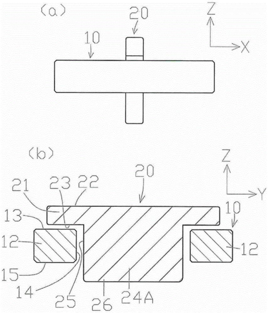
[0123] In the first embodiment example, the lower end 23 of the arm portion of the normal mode core is in contact with the outer shape guide portion 54 of the bottomed square cylindrical portion 51, and the normal mode magnetic core 20 is positioned on the bottomed square cylindrical portion 51, but in the second In the embodiment example, the leg portion 24B of the normal mode core abuts against the abutting portion 52 and is positioned.
[0124] That is, in the first embodiment example, in figure 1 In (d), in the state where the common mode magnetic core 10 and the case 50 are integrally fixed, the shape guide portion 54 in the insertion dire...
no. 3 Embodiment approach example
[0137] Next, according to Figure 10 or Figure 11 The configuration of the line filter according to the third embodiment of the present invention will be described.
[0138] exist Figure 10 or Figure 11 in, for with Figure 1 to Figure 9 The same symbols are given to the same members in , and descriptions of these members are omitted.
[0139] The normal mode core 20 of the second embodiment is T-shaped having two arms 21 and one leg 24B, but the normal mode core 27 of the third embodiment is formed in a square shape.
[0140] Such as Figure 11 (a) shown (from Figure 10When viewed from the direction G-G in (a), the length of the normal mode core 27 in the insertion direction is formed to be longer than the length of the common mode core 10 in the insertion direction, and the common mode core 10 is overlapped with the normal mode core 27 in the insertion direction. the central. Additionally, if Figure 11 As shown in (b), the magnetic route between the common mode...
PUM
 Abstract
Description
Claims
Application Information
 - R&D
- Intellectual Property
- Life Sciences
- Materials
- Tech Scout
- Unparalleled Data Quality
- Higher Quality Content
- 60% Fewer Hallucinations
Browse by: Latest US Patents, China's latest patents, Technical Efficacy Thesaurus, Application Domain, Technology Topic, Popular Technical Reports.
© 2025 PatSnap. All rights reserved.Legal|Privacy policy|Modern Slavery Act Transparency Statement|Sitemap|About US| Contact US: help@patsnap.com