Condenser heat source based thermoelectric power generation apparatus

A technology of thermoelectric power generation and thermoelectric power generation sheets, which is applied in the direction of generators/motors, electrical components, etc., can solve the problems of heat energy waste and inability to recycle condensers, and achieve the effects of reducing space, improving power generation efficiency, and good market prospects

Inactive Publication Date: 2016-08-24
ZHEJIANG GEMCORE TECH
View PDF12 Cites 2 Cited by
  • Summary
  • Abstract
  • Description
  • Claims
  • Application Information

AI Technical Summary

Problems solved by technology

[0003] The purpose of the present invention is to provide a device for thermoelectric power generation using a semiconductor thermoelectric sheet, aiming at the fact that the heat energy waste of the existing condenser cannot be recycled.

Method used


Image

  • Condenser heat source based thermoelectric power generation apparatus
  • Condenser heat source based thermoelectric power generation apparatus
  • Condenser heat source based thermoelectric power generation apparatus

Examples


Embodiment 1

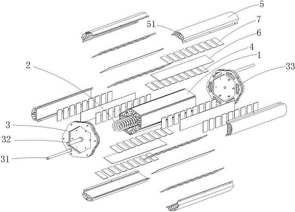
[0025] Such as figure 1 , figure 2 As shown, this embodiment is mainly composed of a casing 1, a condenser tube 2, a side cover 3, a first power generation chip 4, a heat dissipation water tank 5, a vapor chamber 6, and a second power generation chip 7. Wherein, the condenser is composed of a shell 1 and a condenser tube 2, forming a water-cooled condenser. Condenser tube 2 is a spiral shape, with a hollow tube structure that circulates the refrigerant inside. When the compressor is working, it compresses the steam evaporated by the evaporator to increase the surface temperature of the condenser tube 2. 2 for efficient use of heat, we place the condenser tube 2 in the inner cavity of the shell 1, fill the cavity with a heat-conducting liquid, such as water, oil, etc., and install two symmetrical sides with screws at both ends of the shell 1 Cover 3 for sealing. At the same time, the side cover 3 is provided with a hollow side tube 31 and a center tube 32, which run through...

Embodiment 2

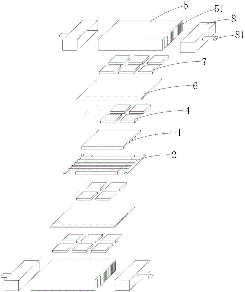
[0039] Such as image 3As shown, this embodiment is mainly composed of a housing 1, a condenser tube 2, a first power generation chip 4, a heat dissipation tank 5, a vapor chamber 6, a second power generation chip 7, an end cover 8, and the like. Among them, the condenser has a shell 1 and a condenser tube 2 to form a flat-plate condenser. The condensation pipe 2 is a series-parallel structure in the shape of a hollow tube to enlarge the contact area with the shell 1 . The shell 1 is divided into upper and lower parts, and is provided with a groove corresponding to the tubular size of the condenser 2. After being closed, the condenser tube 2 is in close contact with the shell 1. In order to improve the heat conduction efficiency, the condenser tube can be welded and / or bonded and solidified. 2 is installed in the housing 1.

[0040] On the upper and lower surfaces of the shell 1 are respectively installed thermoelectric power generation structures with the same structure, on...


PUM


Abstract

Disclosed is a condenser heat source based thermoelectric power generation apparatus. The thermoelectric power generation apparatus comprises a water-cooling or flat plate type condenser and semiconductor thermoelectric power generation chips, wherein at least one layer of the semiconductor thermoelectric power generation chips are directly or indirectly fixed on the surface of the water-cooling or flat plate type condenser; and a radiating apparatus is fixed above the thermoelectric power generation chip on the outermost side. Due to uniform-temperature plates, the heat from the heat source can be rapidly and uniformly transferred to the uniform-temperature plates; then the uniform-temperature plates transfer the uniform heat to the hot ends of the thermoelectric power generation chips; the heat conductive area can be enlarged and the temperature differences of the power generation chips can be increased, so that more thermoelectric power generation chips can be used for realizing the uniform power generation so as to improve the power generation efficiency.

Description

technical field [0001] The invention belongs to an energy-saving device for recovering heat energy, in particular to a device for thermoelectric power generation by using semiconductor thermoelectric power generation sheets and using condenser heat energy. Background technique [0002] The condenser is a component of the refrigeration system and is a type of heat exchanger that can convert steam into liquid and transfer the heat in the tube to the air near the tube in a very fast way. The working process of the high temperature of the condenser is an exothermic process. This leads to the waste of heat energy, so there is an urgent need for a device that can utilize the heat energy. Since the efficiency of the semiconductor chip has also been greatly improved, the practical application of the present invention has become a reality, and the present invention is applied in this context. born. Contents of the invention [0003] The object of the present invention is to provi...

Claims


Application Information

Patent Timeline
IPC IPC(8): H02N11/00
CPCH02N11/002
Inventor 诸建平
Owner ZHEJIANG GEMCORE TECH
Why Eureka
Try Eureka