
Design method for numerical control milling intelligent clamp for thin-wall structural piece

A thin-walled structural part, CNC milling technology, applied in metal processing equipment, manufacturing tools, metal processing and other directions, can solve problems such as poor adsorption effect, difficult to control clamping force, reduce clamping error, facilitate transportation and Maintenance, the effect of reducing chatter

Inactive Publication Date: 2016-08-31
SHENYANG AEROSPACE UNIVERSITY
View PDF5 Cites 6 Cited by
  • Summary
  • Abstract
  • Description
  • Claims
  • Application Information

AI Technical Summary

Problems solved by technology

The simple mechanical clamping method is affected by human factors, and the clamping force is not easy to control
There are also some planar single-sided structures and small-thickness structural parts that are clamped by vacuum adsorption, and the vacuum adsorption method has poor adsorption effect on structural parts with large thickness and double-sided structure.

Method used


Image

  • Design method for numerical control milling intelligent clamp for thin-wall structural piece
  • Design method for numerical control milling intelligent clamp for thin-wall structural piece
  • Design method for numerical control milling intelligent clamp for thin-wall structural piece

Examples


Embodiment Construction

[0024] Step 1:

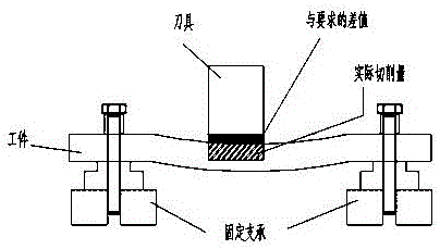
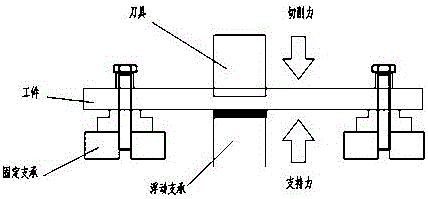
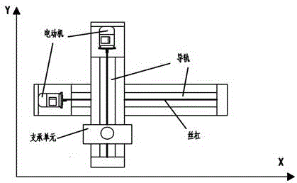
[0025] Such as Figure 1-8 As shown, the smart fixture for CNC milling of thin-walled structural parts includes a base 1, a fixed support 2, an X-direction transmission device 3, a Y-direction transmission device 4, and a support unit structure 5. The design steps 1: (1), XY direction plane The moving structure includes an X-direction feed structure and a Y-direction feed structure. The X-direction feed structure and the Y-direction feed structure are respectively composed of a base structure, a guide rail, a screw, and a motor. The Y-direction feed structure is set on the X-direction structure. The guide rail is driven by a screw, and the supporting unit is placed on the guide rail of the Y-direction structure, and the two-axis linkage is completed by using the screw drive, and the supporting unit structure moves in the XY direction; the XY-direction translation structure can realize the supporting unit "following" the tool The part that is fed together. Fo...


PUM


Abstract

The invention discloses a design method for a numerical control milling intelligent clamp for a thin-wall structural piece. The design method is characterized in that firstly, an X-Y direction translation motion structure comprises an X-direction feed structure and a Y-direction feed structure; secondly, a support unit structure comprises a Z-direction supporting structure and a contact unit structure of the Z-direction supporting structure; thirdly, a clamp overall structure comprises a clamp base; and fourthly, an intelligent clamp system comprises a computer for obtaining the feed path and conducting storage and analysis and a displacement sensor arranged below a workpiece and used for obtaining and recording the initial position of the workpiece before machining. The design method has the advantages that a support manner with fixed supports as an auxiliary part and movable floating supports as a main part is adopted, the fixed supports are located on the periphery of the workpiece, and after machining is finished, parts deforming due to fixed clamping can be removed, and the precision of a component is not affected. During initial clamping, due to the joint action of the fixed supports and the floating supports, the workpiece is stressed evenly, unnecessary residual stress is prevented from being generated, accordingly, the clamping error is reduced, and the machining precision is improved.

Description

technical field [0001] The invention relates to the field of processing technology, in particular to a design method of an intelligent fixture for numerically controlled milling of thin-walled structural parts in aerospace. Background technique [0002] Innovative development and design of a new type of intelligent fixture system for CNC milling of thin-walled structural parts. This invention realizes that the present invention can realize the supporting force provided by the moving support to offset the cutting force in the thickness direction brought by the tool, thereby greatly reducing the deformation of the workpiece due to the cutting force and improving the machining accuracy. In addition, the support The vibration isolation design in the unit can also reduce cutting chatter and reduce workpiece surface errors. The mobile support design and the detachable design of each module are compatible with the processing of various thin-walled structural parts to the greatest ...

Claims


Application Information

Patent Timeline
Patent Type & Authority Applications(China)
IPC IPC(8): B23Q5/40B23Q15/013B23Q3/06
CPCB23Q3/065B23Q5/40B23Q15/013
Inventor 杨靖宇张智捷
Owner SHENYANG AEROSPACE UNIVERSITY
Learn More