Continuous production equipment and production method for thermal insulation layer of plastic thermal insulation pipeline

A technology for thermal insulation pipelines and production equipment, applied in the pipeline field, can solve the problems of thermal pipeline length limitation, low construction and installation efficiency, hidden safety hazards, etc., and achieve the effect of continuous production

Inactive Publication Date: 2016-08-31
GOODY SCI & TECH CO LTD
View PDF2 Cites 4 Cited by
  • Summary
  • Abstract
  • Description
  • Claims
  • Application Information

AI Technical Summary

Problems solved by technology

[0003] Since the existing thermal pipelines all adopt the production method of filling foam material between the working inner tube and the protective outer layer to form an insulation layer, the length of the thermal pipeline obtained by the production is limited, that is, because the insulation layer cannot realize continuous production, As a result, the thermal pipeline cannot achieve continuous production
The thermal pipelines produced section by section need to be installed section by section during construction and installation, which not only leads to low production efficiency, but also leads to low construction and installation efficiency, and the many connection points between various sections of thermal pipelines cause system safety hazards

Method used


Image

  • Continuous production equipment and production method for thermal insulation layer of plastic thermal insulation pipeline
  • Continuous production equipment and production method for thermal insulation layer of plastic thermal insulation pipeline
  • Continuous production equipment and production method for thermal insulation layer of plastic thermal insulation pipeline

Examples


Embodiment Construction

[0020] The present invention will be further described below in conjunction with the accompanying drawings and specific embodiments, so that those skilled in the art can better understand the present invention and implement it, but the examples given are not intended to limit the present invention.

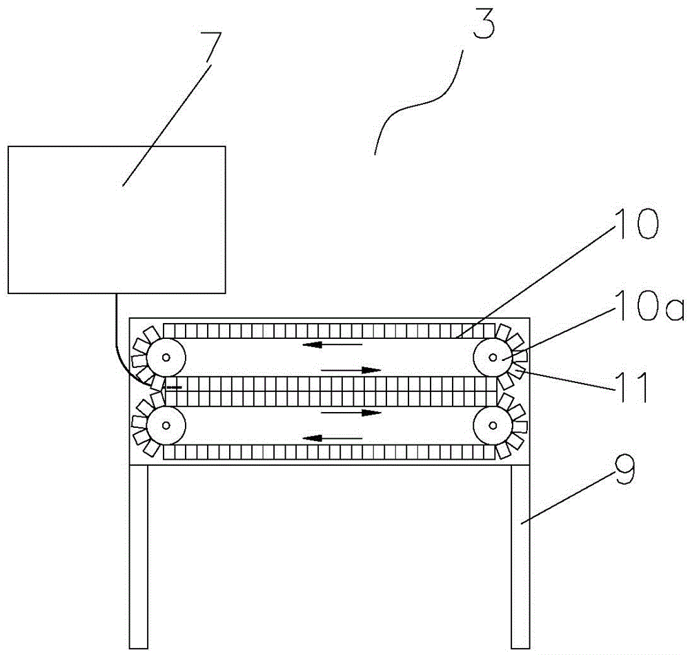
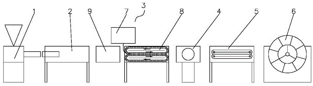
[0021] Such as figure 1 Shown is a schematic structural view of an embodiment of the continuous production equipment for the insulation layer of plastic insulation pipes of the present invention. The continuous production equipment for the insulation layer of plastic insulation pipes in this embodiment includes a foaming machine 7 and an insulation layer forming device 8 for continuously wrapping the insulation layer on the working inner pipe.

[0022] The insulating layer forming device 8 of the present embodiment includes a frame 9, on which two conveyor belt mechanisms are provided, and the conveyor belt mechanism includes at least two pulleys and a conveyor belt 10 sleeved on ...


PUM


Abstract

The invention discloses continuous production equipment for a thermal insulation layer of a plastic thermal insulation pipeline. The continuous production equipment comprises a foaming machine and a thermal insulation layer molding device, wherein the thermal insulation layer molding device comprises a rack; two conveyer belt mechanisms are arranged on the rack; each conveyor belt mechanism comprises belt pulleys and a conveyer belt mounted on the belt pulleys in a sleeving manner; two adjacent belt pulleys are working belt pulleys of which a central connection line is parallel to the feed direction of a working inner pipe; thermal insulation layer molding mold units are mounted on the conveying belt; semicircular grooves are formed in the end faces of one ends, back to the conveying belts, of the thermal insulation layer molding mold units; the thermal insulation layer molding mold units which are respectively arranged on the two conveyer belts and are located between the two corresponding working belt pulleys are matched with each other and are spliced through the semicircular grooves to form a round-tube-shaped thermal insulation layer molding channel for allowing the working inner pipe to pass through; the geometric dimension of the thermal insulation layer molding channel is larger than that of the inner working pipe; and a foaming material output port of the foaming machine is in the thermal insulation layer molding channel. The invention further discloses a continuous production method for the thermal insulation layer of the plastic thermal insulation pipeline.

Description

technical field [0001] The invention belongs to the technical field of pipelines, and in particular relates to continuous production equipment and a production method for the insulation layer of plastic insulation pipelines. Background technique [0002] Traditional heat pipes are generally composed of steel working inner pipes, anti-corrosion layers, insulation layers and protective layers. A bracket is installed between the steel pipe straight pipe and the protective outer pipe to maintain the coaxial state between the steel pipe straight pipe and the protective outer pipe, and then the insulation layer is poured. Therefore, due to the structural characteristics of the existing thermal pipeline, only one section of straight pipe can be produced at a time, and it is connected by section-by-section electric welding at the time of production and installation. At present, some insulation pipes using plastic pipes as working inner pipes have appeared on the market, but they on...

Claims


Application Information

Patent Timeline
Patent Type & Authority Applications(China)
IPC IPC(8): B29C44/32B29C44/30B29C69/02B29L23/00
CPCB29C44/324B29C44/30B29C69/02B29L2023/22
Inventor 付志敏覃海波李贤梅
Owner GOODY SCI & TECH CO LTD
Why Eureka
Try Eureka