A blast furnace main belt material flow tracking control method and device

A tracking control and belt technology, applied in the field of blast furnace smelting, can solve problems such as easy damage of material flow detectors and equipment malfunctions, and achieve the effects of reducing production failures, stabilizing the control process, and avoiding equipment malfunctions.

Active Publication Date: 2019-04-23
武汉钢铁有限公司
View PDF3 Cites 0 Cited by
  • Summary
  • Abstract
  • Description
  • Claims
  • Application Information

AI Technical Summary

Problems solved by technology

[0003] The present invention provides a method and device for tracking and controlling the material flow of the main belt of a blast furnace, which solves the technical problem in the prior art that the material flow detector is easily damaged and causes equipment malfunction, and can reduce production failures caused by the failure of the material flow detector

Method used


Image

  • A blast furnace main belt material flow tracking control method and device
  • A blast furnace main belt material flow tracking control method and device

Examples


Embodiment 1

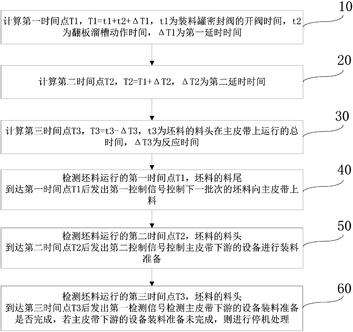
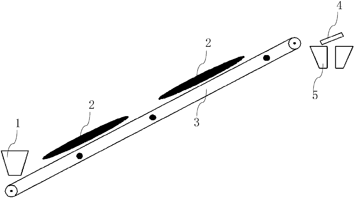
[0061] see figure 1 and figure 2 , the valve opening time t1 of the sealing valve 1 of the charging tank is 2s, the action time t2 of the flap chute 4 is 2s, and the time t3 of the billet 2 moving from the discharge point to the discharge point is 30s. The first delay time ΔT1 is 2s, the second delay time ΔT2 is 2s, and the response time ΔT3 is 10s. It is calculated that the first time point T1 is 6s, the second time point T2 is 8s, and the third time point T3 is 20 seconds.

[0062] During the working process, the first control signal is sent out before the fourth control signal, and the first control signal is used to control the feeding of the next batch of blanks 2 to the main belt 3 . The second control signal is sent out before the fifth control signal, and the equipment downstream of the main belt 3 is controlled by the second control signal to prepare for loading. The first detection signal is sent before the second detection signal, and the first detection signal ...

Embodiment 2

[0064] see figure 1 and figure 2 , the valve opening time t1 of the sealing valve 1 of the charging tank is 2s, the action time t2 of the flap chute 4 is 2s, and the time t3 of the billet 2 moving from the discharge point to the discharge point is 28s. The first delay time ΔT1 is 2s, the second delay time ΔT2 is 2s, and the response time ΔT3 is 10s. It is calculated that the first time point T1 is 6s, the second time point T2 is 8s, and the third time point T3 is 18 seconds.

[0065] During the working process, the first control signal is sent after the fourth control signal, and the fourth control signal is used to control the feeding of the next batch of blanks 2 to the main belt 3 . The second control signal is sent out before the fifth control signal, and the equipment downstream of the main belt 3 is controlled by the second control signal to prepare for loading. The first detection signal is sent out after the second detection signal, and the second detection signal ...

Embodiment 3

[0067] see figure 1 and figure 2 , the valve opening time t1 of the sealing valve 1 of the charging tank is 3s, the action time t2 of the flap chute 4 is 3s, and the time t3 of the billet 2 moving from the discharge point to the discharge point is 25s. The first delay time ΔT1 is 2s, the second delay time ΔT2 is 3s, and the response time ΔT3 is 10s. It is obtained that the first time point T1 is 8s, the second time point T2 is 11s, and the third time point T3 is 15 seconds.

[0068] During the working process, the first control signal is sent out before the fourth control signal, and the first control signal is used to control the feeding of the next batch of blanks 2 to the main belt 3 . The second control signal is sent after the fifth control signal, and the equipment downstream of the main belt 3 is controlled by the fifth control signal to prepare for loading. The first detection signal is sent before the second detection signal, and the first detection signal control...


PUM


Abstract

The invention relates to a blast furnace main belt material flow tracking control method and a device. The method comprises the following steps: a first time point, a second time point and a third time point are calculated; after a material tail reaches the first time point, a next batch of blanks is controlled to be loaded on a main belt; after a material head reaches the second time point, equipment downstream of the main belt is controlled to prepare for loading; after the material head reaches the third time point, whether preparation for loading by the equipment downstream of the main belt is completed is detected; and if the loading preparation by the equipment downstream of the main belt is not completed, shutdown treatment is performed. The device consists of a first calculating unit, a second calculating unit, a third calculating unit, a first processing unit, a second processing unit, a third processing unit, first material flow detecting equipment, second material flow detecting equipment and third material flow detecting equipment. The blast furnace main belt material flow tracking control method and device provided by the invention can prevent the technical problem of misoperation of the equipment caused by damage of the material flow detectors, and reduces production faults caused by the faults of the material flow detectors.

Description

technical field [0001] The invention relates to the technical field of blast furnace smelting, in particular to a method and device for tracking and controlling the material flow of a blast furnace main belt. Background technique [0002] In the blast furnace ironmaking process, the main feeding belt is the core equipment connecting the top of the blast furnace and the bottom of the raw material trough, and the ore and coke are transported to the top tank 5 through the main belt. The material flow detection point on the main belt is detected by the material flow detector, but the material flow cannot be tracked. Due to the harsh environment of the main belt area under the groove, dust and iron powder permeate for a long time, which can easily cause a short circuit to the ground of the electrical equipment. The material flow detector has the following problems in the use process: first, the environmental requirements are relatively high, and dust and iron powder sometimes ca...

Claims


Application Information

Patent Timeline
Patent Type & Authority Patents(China)
IPC IPC(8): C21B5/00
CPCC21B5/006
Inventor 程志蒋辉秦伟陈连聪刘浩程曦杨志刚
Owner 武汉钢铁有限公司
Why Eureka
Try Eureka