Vibrating and twisting combined impact speeding-up drill

A technology of drill bit and impact pendulum, applied in the direction of drill bit, drill pipe, drill pipe, etc., can solve the problems of weak impact force, limited installation size, damage to the drill bit, etc., and achieve the effect of being easy to break, avoiding stick-slip, and protecting the drill bit.

Inactive Publication Date: 2016-08-31
YANGTZE UNIVERSITY +2
View PDF5 Cites 11 Cited by
  • Summary
  • Abstract
  • Description
  • Claims
  • Application Information

AI Technical Summary

Problems solved by technology

However, the small vibration impact is not enough to significantly increase the rock breaking efficiency, and the excessive impact will damage the drill bit itself, resulting in shortened life of the drill bit
[0003] At present, commonly used vibration and impact tools, such as rotary punching tools combined with screw motors, have a weak impact force due to the very limited installation size, and the drilling tool carried under the screw motor further attenuates the vibration impact force, increasing the rotary force. The impact force will increase the length of the tool, affect the orientation, and cause premature fatigue damage to the screw drive shaft
Currently commonly used torsional impactors need to be connected to the drill bit through threads, so the weight of the lower end of the tooth is relatively large, resulting in a large attenuation of torsional impa

Method used


Image

  • Vibrating and twisting combined impact speeding-up drill
  • Vibrating and twisting combined impact speeding-up drill
  • Vibrating and twisting combined impact speeding-up drill

Examples


Embodiment Construction

[0045] In order to make the objectives, technical solutions and advantages of the present invention clearer, the present invention will be described in further detail below in conjunction with the accompanying drawings and embodiments. It should be understood that the specific embodiments described here are only used to explain the present invention and are not intended to limit the invention.

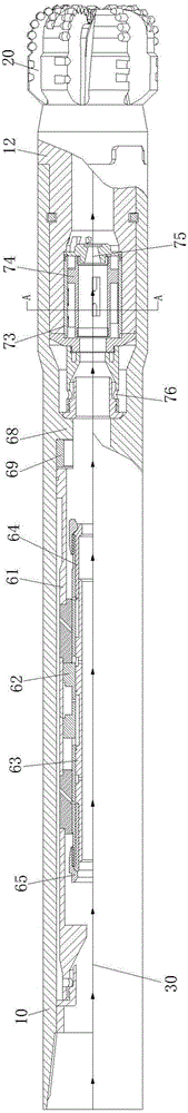
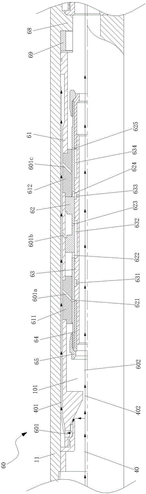
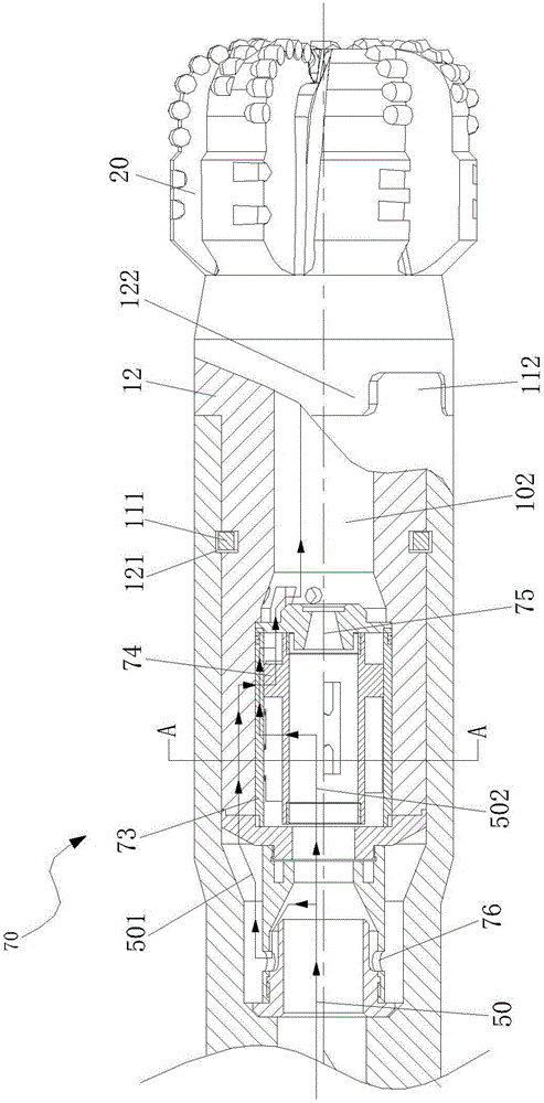
[0046] Such as Figure 1 to Figure 9 As shown, the present invention provides a vibration-torsion compound impact speed-increasing drill bit. The vibration-torsion compound impact speed-increasing drill bit is arranged on a hydraulic device, and the hydraulic device provides circulating hydraulic power for the vibration-torsion compound impact speed-increasing drill bit. The vibration-torsion composite impact speed-up drill bit includes a drill string 10, a drill bit 20 arranged at one end of the drill string 10, and a hydraulic passage 30 arranged along the length direction of the dri...


PUM


Abstract

The invention discloses a vibrating and twisting combined impact speeding-up drill. The vibrating and twisting combined impact speeding-up drill comprises a drill column, a drill bit arranged at one end of the drill column, and a hydraulic passageway arranged in the length direction of a drill column body. The hydraulic passageway comprises an axial hydraulic passageway body and a twisting direction hydraulic passageway body which are sequentially arranged from top to bottom in the overall flowing direction of the hydraulic passageway. The axial hydraulic passageway body is provided with an axial vibration impact system for providing axial vibration for the drill bit, the twisting direction hydraulic passageway body is provided with a twisting direction vibration impact system for providing twisting direction vibration for the drill bit, and the axial vibration impact system and the twisting direction vibration impact system both conduct power transmission through the drill column. The axial vibration impact system and the twisting direction vibration impact system are organically combined into the same drill column, a non-thread type drill bit assembly is clamped to the drill column, and therefore local stress is avoided effectively. Axial vibration impact and twisting direction vibration impact directly act on a drill bit body, and energy attenuation is avoided to the greatest extent.

Description

technical field [0001] The invention relates to an oil drilling and production downhole tool, in particular to a vibration-torsion compound impact speed-increasing drill bit. Background technique [0002] The vibration shock in the axial direction near the drill bit and the vibration shock in the torsional direction can effectively help the PDC drill bit compact to eat into the rock, cut the rock, vibrate and break the rock, and prevent the drill bit from slipping on the rock. However, the small vibration impact is not enough to significantly increase the rock-breaking efficiency, and the excessive impact will damage the drill bit itself, resulting in shortened life of the drill bit. [0003] At present, commonly used vibration and impact tools, such as the rotary punching tool combined with the screw motor, have a weak impact force due to the very limited installation size, and the drilling tool carried under the screw motor further attenuates the vibration impact force, in...

Claims


Application Information

Patent Timeline
IPC IPC(8): E21B10/36E21B17/00E21B4/16
CPCE21B4/16E21B10/36E21B17/00
Inventor 王越之王天巧
Owner YANGTZE UNIVERSITY
Why Eureka
Try Eureka