Electronic ignition time-delay fireworks system

An electronic ignition and fireworks technology, applied in pyrotechnics, electric fuzes, weapon accessories, etc., can solve problems such as error-prone, safety hazards, and large dispersion of launch time, so as to improve ignition and delay accuracy, reduce safety risks, and streamline The effect of complexity

Pending Publication Date: 2016-08-31
WUXI SHENGJING ELECTRONICS TECH CO LTD
View PDF0 Cites 0 Cited by
  • Summary
  • Abstract
  • Description
  • Claims
  • Application Information

AI Technical Summary

Problems solved by technology

However, in the process of production and use, there are the following shortcomings in safety and reliability, which are likely to cause major production safety accidents and discharge failure accidents
[0005] Disadvantage 1: ignition method
[0006] Disadvantage 2: Time Accuracy
For the firework shells fired with open flames, there is a large dispersion in the launch time. Although the firework shells fired by the electric ignition head have a small dispersion, the blooming time accuracy of the firework shells is determined by the fuse / wire. Burning rate is controlled, and there is also a large time dispersion, generally hundreds of milliseconds to several seconds, which cannot meet the time accuracy requirements for large-scale fireworks shows
[0007] Disadvantage three: discharge method
In order to meet the scale requirements of large-scale activities, most of the existing fireworks bombs use the method of electric ignition head to realize program-controlled launch, but each fireworks bomb needs to lead out 2 wires, and N rounds of fireworks bombs need 2N wires to the dedicated ignition device, which limits the number of shells loaded by a single network, and the on-site workload is huge and error-prone
[0008] Disadvantage 4: Social Security Management
Due to the low requirements of the existing fireworks shells for the people who set them off, if the fireworks shells accidentally flow out to the society, it will bring serious safety hazards. Therefore, the country has implemented strict full-circulation management for large-scale fireworks shells, and the management results are relatively high.

Method used


Image

  • Electronic ignition time-delay fireworks system
  • Electronic ignition time-delay fireworks system
  • Electronic ignition time-delay fireworks system

Examples


Embodiment Construction

[0024] Specific embodiments of the present invention are described in detail below, but it should be understood that the protection scope of the present invention is not limited by the specific embodiments.

[0025] Unless expressly stated otherwise, throughout the specification and claims, the term "comprise" or variations thereof such as "includes" or "includes" and the like will be understood to include the stated elements or constituents, and not Other elements or other components are not excluded.

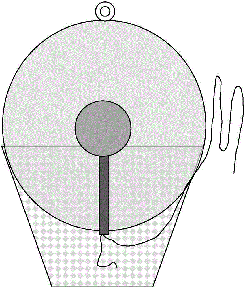
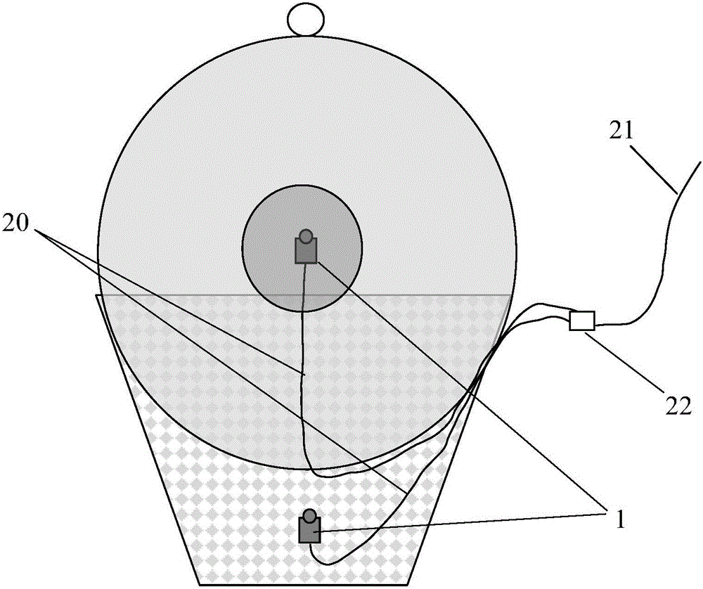
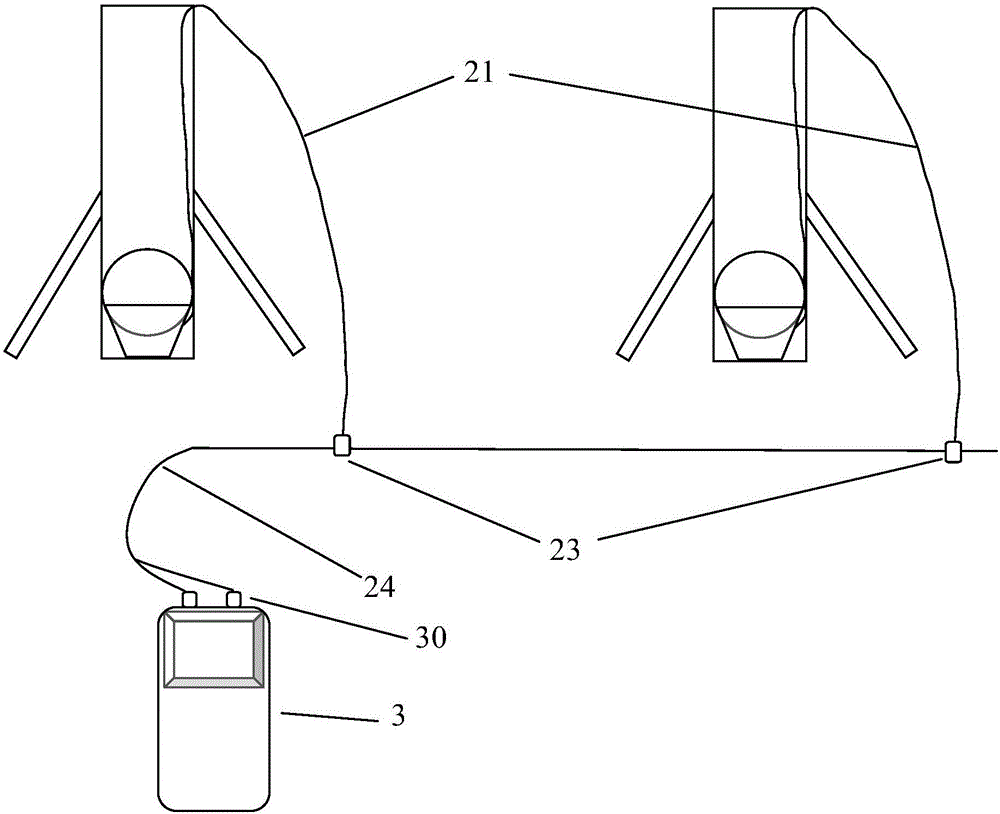
[0026] Such as Figure 2-3 , 5-6, the electronic ignition delay fireworks system includes: electronic delay ignition module 1, field bus network 2, host computer 3; In the medicine; the electronic delay ignition module 1 is connected with the host computer 3 through the field bus network 2; the field bus network 2 includes a double-core wire 20, a communication pin 21, a connecting device 22, a bus connection card 23, and a field communication Bus bar 24; the two-core electr...


PUM


Abstract

The invention discloses an electronic ignition time-delay fireworks system. Electronic time-delay ignition modules are arranged in igniting powder and blasting explosive of a fireworks cartridge case separately. The electronic time-delay ignition modules are connected with an upper computer by a field bus network. Twin-core cables are connected with the electronic time-delay ignition modules. The two sets of twin-core cables are drawn from two sets of electronic time-delay ignition modules separately and connected with a connecting device. A set of communication leg wire is drawn from the connecting device, and two sets of twin-core cables are connected to the communication leg wire in parallel in the connecting device. The communication leg wire is connected with a bus wiring card. The communication leg wires of different fireworks cartridge cases are connected to a field communication busbar in parallel by the bus wiring cards, and the field communication busbar is connected with terminals on the upper computer. The system has the advantages of being high in usage threshold, low in safety risk, high in ignition and time-delay accuracy, easy to install, high in flexibility and like.

Description

Technical field: [0001] The invention belongs to the field of electronic ignition control, in particular to an electronic ignition delay fireworks system. Background technique: [0002] Fireworks are an important part of our country's folk culture. They play an indispensable role in folk weddings, funerals, weddings, festivals, performances at large-scale events, and national grand celebrations. [0003] Most of the traditional fireworks use open flame ignition and fuse / pipe delay method, such as figure 1 As shown, the principle is to ignite the propellant by the energy after the fuze is ignited, and at the same time ignite the fuse tube / line of the projectile of the fireworks, and throw the projectile to high altitude through the energy generated by the combustion of the propellant, and the projectile is in the process of rising In the process, the burning time of the squib / line with a lower burning rate is used for timing. When the squib / line burns, the blasting powder in...

Claims


Application Information

Patent Timeline
Patent Type & Authority Applications(China)
IPC IPC(8): F42C11/06F42B4/00
CPCF42C11/06F42B4/00
Inventor 侯颖陈广殷婷
Owner WUXI SHENGJING ELECTRONICS TECH CO LTD
Why Eureka
Try Eureka