Radio frequency power amplification circuit

A technology for amplifying circuits and radio frequency power, which is applied to power amplifiers, high frequency amplifiers, amplifiers, etc., and can solve problems such as power amplifier efficiency decline

Active Publication Date: 2016-08-31
HISENSE VISUAL TECH CO LTD
View PDF5 Cites 6 Cited by
  • Summary
  • Abstract
  • Description
  • Claims
  • Application Information

AI Technical Summary

Problems solved by technology

[0005] The embodiment of the present invention provides a radio frequency power amplifier circuit, which is used to solve the problem in the prior art that when the output power of the power amplifier is adjusted downward, the efficiency of the power amplifier will decrease accordingly

Method used


Image

  • Radio frequency power amplification circuit
  • Radio frequency power amplification circuit
  • Radio frequency power amplification circuit

Examples


Embodiment 3

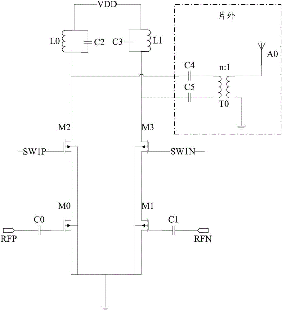
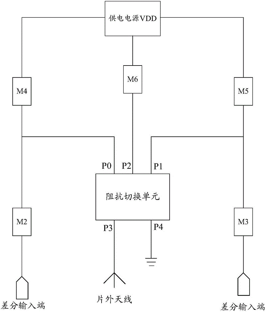
[0062] Embodiment three, the radio frequency power amplifier (PA) circuit that this embodiment provides, is applied in BLE SOC chip, and circuit structure is as follows Figure 4 As shown, it includes: the third capacitor C0 and the fourth capacitor C1 used to isolate the DC part of the input radio frequency signal; the first capacitor C2 and the second capacitor C3; the sixth switch M0, the seventh switch M1, and the first switch group M2 and the second switch group M3, and M0, M1, M2, and M3 are all NMOS transistors; the third switch M4, the fourth switch M5, and the fifth switch M6, and M4, M5, and M6 are all PMOS transistors; and the balun T0 . The first capacitor C2 and the parasitic inductance of the secondary coil of the balun T0 form the first resonant circuit, and the resonant frequency f1 of the first resonant circuit is the operating frequency of the PA circuit, namely sqrt() represents the square root function; the second capacitor C3 and the parasitic inductance...


PUM


Abstract

The present invention discloses a radio frequency power amplification circuit. The radio frequency power amplification circuit comprises a first switch group, a second switch group, an impedance switching unit, a third switch, a fourth switch and a fifth switch; one terminal of the first switch group is connected with one differential input terminal of the circuit, and the other terminal of the first switch group is connected with a first balanced differential port of the impedance switching unit; one terminal of the second switch group is connected with the other differential input terminal of the circuit, and the other terminal of the second switch group is connected with a second balanced differential port of the impedance switching unit; one terminal of the third switch is connected with a power supply, and the other terminal of the third switch is connected with the first balanced differential port of the impedance switching unit; one terminal of the forth switch is connected with the power supply, and the other terminal of the fourth switch is connected with the second balanced differential port of the impedance switching unit; one terminal of the fifth switch is connected with a center tap port of the impedance switching unit, and the other terminal of the fifth switch is connected with the power supply; and impedance conversion of the impedance switching unit is controlled through on or off of the first switch group, the second switch group, the third switch, the fourth switch and the fifth switch.

Description

technical field [0001] The invention relates to the technical field of communication, in particular to a radio frequency power amplifier circuit. Background technique [0002] Bluetooth Low Energy (Bluetooth Low Energy, referred to as BLE) System On Chip (SOC) chip has very high requirements on system power consumption, and the radio frequency transmission link power amplifier (Power Amplifier, referred to as PA) in the BLE SOC chip is usually It is the module that consumes the most power. Therefore, in the design of the Bluetooth BLE SOC chip, the power consumption control of the power amplifier in the radio frequency transmission link is particularly important. [0003] The existing power amplifier circuit such as figure 1 As shown, the RF voltage input signal of the upper stage is input to the power amplifier through the RFP terminal and the RFN terminal respectively in differential form. After amplification, it still adopts the differential form and is output through C4...

Claims


Application Information

Patent Timeline
IPC IPC(8): H03F1/56H03F1/02H03F3/189H03F3/24
CPCH03F1/0211H03F1/56H03F3/189H03F3/245
Inventor 孙响
Owner HISENSE VISUAL TECH CO LTD
Why Eureka
Try Eureka