Pneumatic circulating grain drier

A kind of grain dryer and circulation technology, which is applied in the direction of drying and preserving seeds, food science, etc., can solve the problems of limited application range and processing range, increased drying cost, corn form gelatinization, etc., and achieve saving drying Effects of cost and labor costs, reduction in drying time, and reduction in drying costs

Active Publication Date: 2016-09-07
河北皓凯农业机械有限公司
View PDF9 Cites 3 Cited by
  • Summary
  • Abstract
  • Description
  • Claims
  • Application Information

AI Technical Summary

Problems solved by technology

[0009] This model has entered the market in recent years. The main consumer market of this product is for large-scale grain processing households, especially in the Northeast, Inner Mongolia, and Xinjiang. The farms in the above-mentioned areas are large grain growers, and family farms are relatively large. Many, the drying temperature of this product is high, the grain is mainly corn, other products cannot be dried, the advantage of this product is that the drying capacity is large, the output is high, but the drying cost is also high, its minimum temperature is 180 ℃, The above drying output mainly depends on high-temperature drying. The biggest problem of this product is: ①The dried corn is gelatinized, and the baked product can only be used as feed and cannot be eaten, and the starch yield is also very low; High dry cost; ③High investment; ④Limited scope of use and processing of the product
[0010] Combining the above three products, regardless of their advantages or disadvantages, they are all single-use and limited in application range, and they all use medium drying processing, resulting in an increase in production costs, and the increase in drying costs due to the increase in medium , to pass this input on to the user of the drying equipment

Method used


Image

  • Pneumatic circulating grain drier
  • Pneumatic circulating grain drier

Examples


Embodiment Construction

[0037] Below in conjunction with accompanying drawing and specific embodiment the present invention is described in detail:

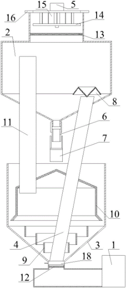
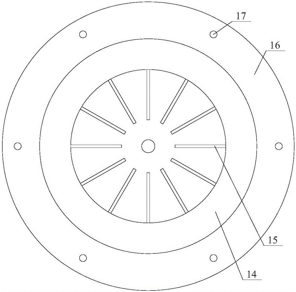
[0038] Specific examples, such as figure 1 and figure 2 As shown, the air suction circulation type grain dryer includes a heat source 1 and an oven. The heat source 1 is a hot blast stove. The hot air outlet of the heat source 1 is connected to the hot air inlet of the oven. The oven includes an upper separation chamber 2, a drying upper beam cylinder 4 and a lower end The lower grain storage room 3 is a funnel-shaped structure. The lower grain storage room 3 is provided with a material inlet, and the upper separation room 2 is provided with a material outlet and an air outlet. During the drying and dehydration process, some harmful substances in the grain are discharged, so that the quality of the grain remains original. A cylindrical louver 9 is added inside the funnel-shaped structure, the louver 9 is fixedly connected with the lower grain storage...


PUM


Abstract

The invention discloses a pneumatic circulating grain drier and belongs to the technical field of drying equipment. A louver board is fixedly connected with a lower grain storage room; a hollow cavity between the louver board and a funnel-shaped structure is a distribution cavity; the hollow structure of the louver board forms an air inlet cavity which communicates with a hot air outlet of a heat source; a drying grain ascending tube passes through the air inlet cavity and reaches to the lower part of the louver board to form a feeding air inlet; the upper end of the drying grain ascending tube is located in an upper separation room; a coaxially arranged weather cap is arranged at the upper part of the drying grain ascending tube; a channel is reserved between the weather cap and the drying grain ascending tube to form a discharge air outlet; and the drying grain ascending tube forms a drying channel by virtue of a fan arranged at the top part of the upper separation room. The grain and hot air are in direct and full contact in the ascending process, so that the grain is dried; the drying effect is good by medium-free suction-type drying; the uniformity is good; the conditions of deterioration such as mildew and sprout of the grain in the links of storage, transportation, processing and the like can be effectively prevented; and the pneumatic circulating grain drier is simple in structure, convenient and fast to use, time-saving and labor-saving.

Description

technical field [0001] The invention belongs to the technical field of drying equipment, and relates to an air suction circulation type grain dryer. Background technique [0002] Most of the grain just harvested by farmers contains high water content. If the water content is not reduced in time, it will lead to mildew and germination and deterioration in storage, transportation, processing and other links. Therefore, grain drying has become an important part of post-production grain. An extremely important condition for food safety storage. Manual drying not only requires a large space, but also in the process of laying the grain on the drying site and storing the grain after drying, it is time-consuming, labor-intensive, and work-efficient, so the grain dryer Came into being. [0003] my country's grain dryer industry started from the initial extensive type and drum type. Since 2012, it has been gradually upgraded to a batch tower type grain dryer. Since 2013, a high towe...

Claims


Application Information

Patent Timeline
Patent Type & Authority Applications(China)
IPC IPC(8): A23B9/08
CPCA23B9/08A23V2002/00A23V2300/10A23V2200/10
Inventor 梁连贵梁凯
Owner 河北皓凯农业机械有限公司
Why Eureka
Try Eureka