CO2 recycling and reusing device after gas well CO2 hydrofracture

A gas well and fracturing technology, which is applied in the field of CO2 recovery and reuse devices after CO2 hydraulic fracturing in gas wells, can solve problems such as aggravating the greenhouse effect and increasing fracturing costs, and achieve the effects of reducing costs, reducing emissions, and reducing environmental protection risks.

Inactive Publication Date: 2016-09-07
PETROCHINA CO LTD
View PDF6 Cites 1 Cited by
  • Summary
  • Abstract
  • Description
  • Claims
  • Application Information

AI Technical Summary

Problems solved by technology

Open fracturing fluid flowback, resulting in CO 2 Escaping into the a

Method used


Image

  • CO2 recycling and reusing device after gas well CO2 hydrofracture

Examples


Embodiment 1

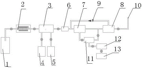
[0025] In order to overcome the open fracturing fluid flowback of existing devices, resulting in CO 2 escape into the atmosphere to aggravate the greenhouse effect and increase the cost of fracturing, the present invention provides such as figure 1 A gas well shown CO 2 CO after hydraulic fracturing 2 Recycling and reuse device, the present invention de-sands and dehydrates the flow-back liquid through manifold step-down and sand-gas-liquid three-phase separator, and then separates CO through three separation membranes 2 and natural gas (CH 4 ), to achieve lower CO ­2 emissions while achieving CO 2 The purpose of recycling and comprehensive utilization.

[0026] A gas well CO 2 The liquid drainage control device after fracturing includes a solid-gas-liquid separator 3, one end of the solid-gas-liquid separator 3 is connected to the gas well 1; the lower end of the solid-gas-liquid separator 3 is connected to a collector for separated solids and liquids, The gas outlet o...

Embodiment 2

[0032] Based on Example 1, in this example, the collectors connected to the lower end of the solid-gas-liquid separator 3 are the fracturing sand collector 4 and the fracturing fluid collector 5 .

[0033] A depressurization retarder 2 is connected between the gas well 1 and the solid-gas-liquid separator 3 .

[0034] In the present invention, once the fracturing of the gas well 1 is completed, the flowback liquid produced from the well passes through the liquid deceleration and depressurization device 2 to throttle the pipeline to protect the downstream test production equipment by reducing the pressure and slowing down the flow rate. After passing through the liquid deceleration and depressurization device 2, the liquid first flows to a solid-liquid-gas three-phase separator 3, and the flowback liquid passes through the solid-liquid-gas three-phase separator 3, and the backflow fracturing fluid in the fracturing flowback liquid is separated by sedimentation The sand is colle...


PUM


Abstract

The invention provides an unloading fluid control device after gas well CO2 fracturing. The device comprises a solid-gas-liquid separator, one end of the solid-gas-liquid separator is connected with a gas well, the lower end of the solid-gas-liquid separator is connected with a collector separating solid and liquid. The air outlet of the solid-gas-liquid separator is connected with a compressor. The other end of the compressor is connected with the inlet of a first-stage separating membrane assembly, and the air outlet on other end of the first-stage separating membrane assembly is connected with a gas outlet. A second-stage separating membrane assembly A is arranged between the first-stage separating membrane assembly and the gas outlet. The air outlet on the lower end of the first-stage separating membrane assembly is also connected with a second-stage separating membrane assembly B. The right end air outlet of the second-stage separating membrane assembly B is connected with the air inlet of the second-stage separating membrane assembly A. Through manifold depressurization and a sand-gas-liquid three-phase separator, the device performs sand strip and dewatering treatment on return unloading fluid, and then through three separating membrane assemblies, CO2 and natural gas (CH4) are separated, so as to achieve objectives of realizing CO2 recycling and comprehensive utilization while reducing CO2 emission.

Description

technical field [0001] The invention relates to a gas well CO 2 CO after hydraulic fracturing 2 Recovery and reuse device for new gas well CO 2 Elimination of CO during drainage after hydraulic fracturing 2 The environmental pollution caused by directly entering the atmosphere after being discharged from the gas well, and at the same time reaching CO 2 The purpose of recycling and comprehensive utilization. Background technique [0002] In order to reduce reservoir damage and improve the gas well fracturing test effect, CO 2 The application scale of hydraulic fracturing in gas fields continues to increase, and single well liquid CO 2 Consumption 180-250m 3 , after fracturing, the fracturing fluid and CO are discharged 2 and CH 4 of mixed gas. Open fracturing fluid flowback, resulting in CO 2 Escaping into the atmosphere exacerbates the greenhouse effect while increasing the cost of fracking. Contents of the invention [0003] The purpose of the patent of the inv...

Claims


Application Information

Patent Timeline
IPC IPC(8): E21B43/34
CPCE21B43/34
Inventor 王亚娟何明舫张燕明马占国肖元相周长静问晓勇胡阳明毕曼郝瑞芬
Owner PETROCHINA CO LTD
Why Eureka
Try Eureka