
Micro-fracture vector scanning method

A scanning method and micro-fracture technology, applied in the field of vector scanning, can solve problems such as high cost, different signal interference, and large noise interference, and achieve the effects of simple and fast construction, noise reduction, and real-time data processing

Active Publication Date: 2016-09-07
北京京援伟达技术有限公司
View PDF5 Cites 1 Cited by
  • Summary
  • Abstract
  • Description
  • Claims
  • Application Information

AI Technical Summary

Problems solved by technology

At present, the most reliable microseismic fracturing detection method is the downhole adjacent observation method, which has strict restrictions and needs to have existing or newly drilled monitoring wells of the same depth adjacent to the fracturing wells, and deploy seismometers in them for observation, which is extremely costly. High, complex implementation process
However, the traditional seismic network observation method on the surface, due to natural tectonic activities or production-induced subterranean micro-fractures, releases extremely weak energy, with magnitude M≤0, usually magnitude M=[-3,-1], which is easily affected by surrounding noise or It is usually impossible to see the prominent seismic response waveform of fracturing micro-ruptures from the surface background noise records, that is, it is impossible to extract the first arrivals of longitudinal and shear waves, and it is difficult to realize the traditional location of the hypocenter based on the first arrivals; even if a large number of Surrounding points are superimposed to highlight this first arrival. Due to the equidistant and dense distribution of points, the noise interference cannot be effectively removed, and the use of small-amplitude longitudinal waves has a monitoring success rate of less than 10%.
[0005] In the invention application 201310218220.7, a micro-fracture vector scanning method is disclosed. The fracturing monitoring stations are sparsely arranged on the surface to effectively locate the underground rupture point. However, because the energy released by the micro-fracture is extremely weak, usually the magnitude M=[-3 , -1], the signal interference received by each sparsely deployed fracturing monitoring station is different, and the signal-to-noise ratio is different, and the noise interference of the scanning results obtained after superposition is still relatively large

Method used


Image

  • Micro-fracture vector scanning method
  • Micro-fracture vector scanning method
  • Micro-fracture vector scanning method

Examples


Embodiment Construction

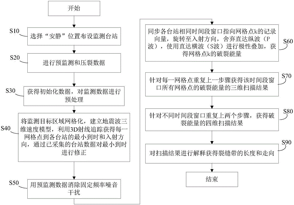
[0034] Introduce the implementation of the micro-fracture vector scanning method of the present invention with the specific implementation operation process of a certain oil well fracturing monitoring project, and its implementation steps are as follows figure 1 shown, including the following steps.

[0035] Step S10: Select a "quiet" location to deploy monitoring stations.

[0036]Within 3km from the projection point of the planned underground fracturing point on the ground, and at the same time, within 1km from the fracturing vehicle group (at the wellhead, not necessarily the above-mentioned projection point), in all azimuths around the projection point, At each distance, M three-component microseismic recorder stations (hereinafter referred to as stations) for monitoring microcracks are discretely arranged at positions with less noise interference. In order to obtain a stronger fracturing signal and improve the signal-to-noise ratio, the closer the station is to the proje...


PUM


Abstract

The invention discloses a micro-fracture vector scanning method, and the method comprises the following steps: (1), obtaining initialization data, and carrying out the preprocessing of micro-fracture monitoring data; (2), carrying out the gridding of a monitoring region, and building a seismic three-dimensional speed model; (3), synchronizing record vectors of all stations towards a grid point k in the same time period window, carrying out polarity superposing, abandoning a nonstop longitudinal wave (P wave) during vector polarity superposing, and employing a nonstop lateral wave (S wave) for weighted polarity superposing; (4), repeatedly carrying out the step (3) for each grid point, and obtaining a three-dimensional scanning result of fracture energy of all grid points in the time period window; (5), repeatedly carrying out the steps (3) and (4) in different time period windows, and obtaining four-dimensional scanning distribution of the fracture energy of a monitoring target region. The method can effectively inhibit noises, enhances useful signals, and achieves the effective positioning of an underground fracture point through scanning underground fracture energy.

Description

technical field [0001] The invention relates to geophysical prospecting microseismic positioning technology, more specifically relates to a vector scanning method for monitoring micro-fractures induced by natural structural activities or production in industrial fields such as petroleum and mineral products. Background technique [0002] Oil and gas mineral reservoirs are generally located at a depth of several hundred to several thousand meters underground, so they have a certain formation pressure. After the well is opened, there is a pressure difference between the well head and the reservoir, and oil and gas will be ejected along the well driven by this pressure difference. However, as the formation pressure near the well gradually releases, the oil and gas eruption gradually weakens until it stops. This is the usual natural kinetic energy release process in the early stage of development. After that, rock fracturing and artificial fractures must be implemented. After ...

Claims


Application Information

Patent Timeline
Patent Type & Authority Applications(China)
IPC IPC(8): G01V1/28G01V1/30G01V1/36
CPCG01V1/28G01V1/301G01V1/362G01V2210/169G01V2210/3248G01V2210/646
Inventor 梁北援
Owner 北京京援伟达技术有限公司
Learn More