Finite element analysis method for thermal-coupled vibration characteristics of impeller structure

A technology of vibration characteristics and analysis methods, applied in special data processing applications, instruments, electrical digital data processing, etc., can solve blade breakage, rotor engine structural damage, aggravate the rubbing thermal shock effect between rotors and stators, and rotor dry friction instability. and other issues to achieve the effect of a reliable theoretical basis

Inactive Publication Date: 2016-09-07
UNIV OF JINAN
View PDF2 Cites 20 Cited by
  • Summary
  • Abstract
  • Description
  • Claims
  • Application Information

AI Technical Summary

Problems solved by technology

At the same time, with the increase of the speed of the rotating machinery, the gap between the rotor and the static parts is continuously reduced, which intensifies the thermal shock effect of rubbing between the

Method used


Image

  • Finite element analysis method for thermal-coupled vibration characteristics of impeller structure
  • Finite element analysis method for thermal-coupled vibration characteristics of impeller structure
  • Finite element analysis method for thermal-coupled vibration characteristics of impeller structure

Examples


Embodiment Construction

[0013] The present invention will be further described with reference to the accompanying drawings and embodiments of the specification.

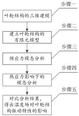
[0014] Such as figure 1 As shown, it is a working flow chart of the finite element analysis method for thermally coupled vibration characteristics of an impeller structure in the present invention. It mainly consists of two parts, which are respectively implemented by two softwares. The detailed steps are as follows:

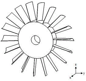
[0015] Step 1: 3D modeling of the impeller structure, using the solidworks parametric modeling method for 3D modeling to obtain a 3D model of the impeller structure, such as figure 2 shown;

[0016] Step 2: Establish the finite element model of the impeller structure, import the 3D model of the impeller structure into the finite element analysis software ANSYS, and complete the design of material properties, parameters, loads and constraints in the pre-processing module of ANSYS software according to the actual working con...


PUM


Abstract

The invention provides a finite element analysis method for thermal-coupled vibration characteristics of an impeller structure. The technical scheme is that the finite element analysis method comprises the following steps: establishing a three-dimensional model of the impeller structure by utilizing a solidworks parameter modelling method; importing the three-dimensional model of the impeller structure into finite element analysis software ANSYS, setting the attributes, parameters, loads and constraints of materials according to the actual working conditions in an ANSYS software pre-processing module, and dividing finite element grids; calculating the first five orders of fixed frequencies of the impeller structure at different rotation speeds through an ANSYS software modal analysis module; calculating the first five orders of fixed frequencies of the impeller structure at different rotation speeds in high-temperature environment through considering the influences of a temperature field; comparing the fixed frequencies in above analysis to obtain the influences, caused by the temperature field, on the vibration characteristics of the impeller structure, so as to provide theoretical basis for the failure mechanism research of the impeller structure under the high-temperature environment.

Description

technical field [0001] The invention relates to a finite element analysis method of a rotating machine, in particular to a finite element analysis method of thermally coupled vibration characteristics of an impeller structure. Background technique [0002] When the rotating machinery is in operation, it is subject to the effects of pneumatic excitation, mechanical excitation, thermal flow field, etc., which can easily cause the vibration of the whole mechanical structure, and make the body, rotor system, accessory system, main bearing and other components have obvious vibration responses. At the same time, with the increase of the rotating speed of the rotating machinery, the gap between the rotating and static parts is continuously reduced, which intensifies the thermal shock effect of rubbing between the rotor and the stator and the dry friction instability of the rotor. Severe thermal effects will cause blade breakage, rotor instability and The destruction of the engine s...

Claims


Application Information

Patent Timeline
IPC IPC(8): G06F17/50
CPCG06F30/17G06F30/23
Inventor 赵慧颖门秀花张琨
Owner UNIV OF JINAN
Why Eureka
Try Eureka