Switching power supply feedback control circuit and single-stage PFC efficient constant current power supply drive circuit
What is Al technical title?
Al technical title is built by PatSnap Al team. It summarizes the technical point description of the patent document.
A switching power supply and feedback control technology, applied in the field of electronics, can solve the problems of inability to eradicate 100HZ ripple, low output current ripple, and inability to take into account low ripple, etc., achieving high cost performance, large volume, and low cost.
Active Publication Date: 2016-09-07
遍发照明(上海)有限公司 +1
View PDF6 Cites 8 Cited by
Summary
Abstract
Description
Claims
Application Information
AI Technical Summary
This helps you quickly interpret patents by identifying the three key elements:
Problems solved by technology
Method used
Benefits of technology
Problems solved by technology
But it can't take into account the requirements of low ripple and no flicker
[0006] The third mode is valley-filling PFC calibration. This topology is a bit simple, cheap, and the output current ripple is low (but the 100HZ ripple cannot be eradicated). The disadvantage is that it is large in size and low in power. It is only suitable for LEDs within 20W. drive
Method used
Image
Click on the blue label to locate the original text in one second.
Reading with bidirectional positioning of images and text.
Examples
Embodiment 1
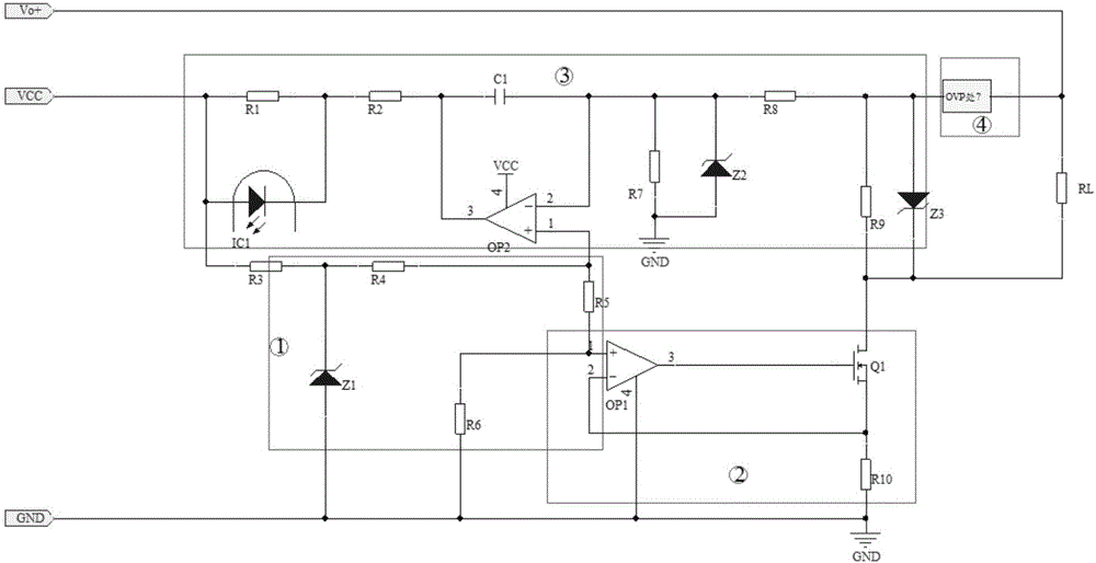
[0042] see figure 2 , which shows the specific circuit schematic diagram of the switching power supply feedback control circuit for constant current and constant voltage to eliminate ripple provided by this example. It can be seen from the figure that the constant current feedback circuit of this embodiment includes a resistor R1, a resistor R2, a resistor R3, a resistor R4, a resistor R5, a resistor R6, a resistor R7, a resistor R8, a resistor R9, a resistor R10, a capacitor C1, Zener diode Z1, Zener diode Z2, Zener diode Z3, MOS transistor Q1, OVP processing module, optocoupler IC1, operational amplifier OP1, operational amplifier OP2 and load RL.
[0043] The power supply terminal of the operational amplifier OP2, the anode of the optocoupler IC1 at one end of the resistor R1 and one end of the resistor R3 are connected to the output terminal VCC of the power supply module;
[0044] The positive end of the Zener diode Z1, one end of the resistor R6, the ground end of the ...
example 2
[0066] In this example, on the basis of Example 1, the Zener diode Z1 is replaced by a three-terminal Zener tube.
[0067] In contrast, Zener diodes are cheap, PCB wiring is simple, and three-terminal Zener tubes have higher precision.
example 3
[0069] In this example, on the basis of Example 1, the Zener diode Z2 and the Zener diode Z3 are removed, and only the resistor R7 and the resistor R9 are used.
[0070] At this time, the functions of the resistors R7 and R9 are not changed, and the output accuracy is further improved.
PUM
Abstract
The invention provides a switching power supply feedback control circuit and a single-stage PFC efficient constant current power supply drive circuit. The invention discloses a switching power supply feedback control circuit for constant-current and constant-voltage ripple elimination and a high-power factor frequent-flashing free constant-current and constant-voltage drive circuit based on a single-stage PFC chip. The switching power supply feedback control circuit includes a voltage stabilization reference module, a constant current module, a constant voltage feedback module, and a protection module, the voltage stabilization reference module supplies stable and reliable reference voltage source for the non-inverting input ends of the constant current module and the constant voltage feedback module, the constant current module adjusts the circuit current to make the circuit output current constant based on the reference voltage source of the voltage stabilization reference module, the constant voltage feedback module is connected with a PWM control circuit of a primary end and is cooperated with the constant current module to adjust the output voltage, so that the circuit output voltage is constant, and the protection module stabilizes and protects the output voltage. The switching power supply feedback control circuit can solve the problems that the LED drive in the prior art is large in size, high in cost, low in PF value, large in ripple, and frequent in flashing and harmful to eyes, and according to the invention, the LED drive at all power levels within 150W can be covered.
Description
technical field [0001] The invention relates to the field of electronics, in particular to a driving technology of a light emitting diode. Background technique [0002] In order to make light-emitting diodes (LEDs, Light Emitting Diodes) or light strings composed of light-emitting diodes work stably and reliably, two-stage PFC circuits are usually used to ensure their high power factor, low input current harmonic content, and DC / DC converters are optimized for design and so on. [0003] At present, there are many ways to form a constant current power supply circuit with a high power factor PF value, among which three modes are the most common. [0004] Among them, the larger power such as figure 1 The two-pole conversion circuit form shown. This two-stage conversion circuit is composed of two-stage converters: the first stage is a PFC converter, the purpose is to improve the input power factor and suppress the high-order harmonics of the input current; the second stage is...
Claims
Application Information
Patent Timeline
Application Date:The date an application was filed.
Publication Date:The date a patent or application was officially published.
First Publication Date:The earliest publication date of a patent with the same application number.
Issue Date:Publication date of the patent grant document.
PCT Entry Date:The Entry date of PCT National Phase.
Estimated Expiry Date:The statutory expiry date of a patent right according to the Patent Law, and it is the longest term of protection that the patent right can achieve without the termination of the patent right due to other reasons(Term extension factor has been taken into account ).
Invalid Date:Actual expiry date is based on effective date or publication date of legal transaction data of invalid patent.