
Tapered beater for machine-made sand

A technology for dispersing machine and machine-made sand, applied in the direction of solid separation, filter screen, grille, etc., can solve the problems of deformation of the screening device, abnormal screening, low stability of the screening device, etc., to ensure the stability of work, Guarantee work reliability and improve the effect of dispersing efficiency

Active Publication Date: 2016-09-14
国家电投集团江西中业兴达电力实业有限公司
View PDF8 Cites 5 Cited by
  • Summary
  • Abstract
  • Description
  • Claims
  • Application Information

AI Technical Summary

Problems solved by technology

[0002] In the existing machine-made sand cone breaker, after the material enters the breaker, the coarse material and the fine material are often not fully separated, and the coarse material and the fine material cannot be fully sorted. Among them, the unbroken Large pieces of material cannot be crushed for the second time, resulting in insufficient dispersal of the material
At the same time, the screening device in the dispersing machine often has screening abnormalities due to the blockage of the sieve hole by the material, resulting in abnormal operation of the dispersing machine, and the sieving device is prone to deformation after being impacted, and the stability of the sieving device is not high.

Method used


Image

  • Tapered beater for machine-made sand
  • Tapered beater for machine-made sand

Examples


Embodiment 1

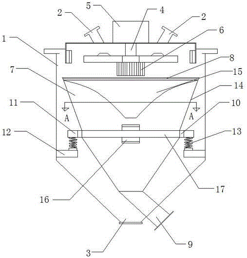
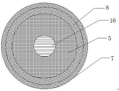
[0018] like figure 1 and figure 2 As shown, a machine-made sand cone breaker includes a feed port 2 located on the upper part of the outer cone shell 1, a fine material port 3 located at the lower part of the outer cone shell 1, and a middle part of the outer cone shell 1. There is a connecting shaft 4, one end of the connecting shaft 4 is driven and connected to the power unit 5, the other end of the connecting shaft 4 is rotated and connected to the wind wheel 6, the lower end of the wind wheel 6 is provided with a screening device 7, and the upper part of the screening device 7 is provided with a feeding 8, the lower part is provided with a coarse material port 9, the side of the screening device 7 is provided with a tight hoop 10, a pair of ears 11 are symmetrically arranged on the tight hoop 10, and the inner wall of the outer cone shell 1 is provided with a supporting part 12, The ear portion 11 and the support portion 12 are connected by a pressure spring 13, and the ...

Embodiment 2

[0024] Embodiment 2 is the same as Embodiment 1, except that the self-lubricating aluminum alloy material is composed of the following components by mass percentage: Fe is 3.4%, Cu is 4.7%, Si is 0.5%, Mg is 1.1%, Cr is 1.5%, Sn is 1.3%, Nb is 0.3%, Bi is 2.0%, the impurity content is not more than 1%, and the balance is aluminum.

Embodiment 3

[0026] Embodiment 3 is the same as Embodiment 1 and Embodiment 2, except that the self-lubricating aluminum alloy material is composed of the following components by mass percentage: Fe is 3.8%, Cu is 5.1%, Si is 0.7%, Mg 1.3% for Cr, 1.5% for Sn, 1.7% for Sn, 0.5% for Nb, 2.2% for Bi, the impurity content is not more than 1%, and the balance is aluminum.

[0027] The self-lubricating aluminum alloy rotating impeller obtained in the above examples is tested and detected, and the Vickers hardness of the self-lubricating aluminum alloy rotating impeller reaches 43-48, the radial crushing strength reaches 185.4-196.7MPa, and the oil content reaches 22%. , has good comprehensive mechanical properties and can meet the requirements of working conditions.


PUM

PropertyMeasurementUnit
crushing strengthaaaaaaaaaa
Vickers hardnessaaaaaaaaaa

Abstract

The invention discloses a tapered beater for machine-made sand. The tapered beater for the machine-made sand comprises feed inlets formed in the upper portion of an outer tapered shell and a fine material port formed in the lower portion of the outer tapered shell. A connecting shaft is arranged on the middle portion of the outer tapered shell. One end of the connecting shaft is in transmission connection with a power unit; and the other end of the connecting shaft is in rotary connection with a wind wheel. The lower end of the wind wheel is provided with a screening unit; a feed port is formed in the upper portion of the screening unit; and a coarse material port is formed in the lower portion of the screening unit. A tight tensioning sleeve is arranged on the side face of the screening unit; and a pair of lug parts is symmetrically arranged on the tight tensioning sleeve. A supporting part is arranged on the inner wall of the outer tapered shell. The lug parts and the supporting part are connected in a matched mode through a pressure ring. By modifying the structure of the screening unit, the screening unit can elastically move up and down to absorb impact force of materials; the screening unit is prevented from deforming and blocking of sieve holes by the materials is prevented; the work stability of the screening unit is guaranteed; complete separation of fine materials and coarse materials is achieved; at the same time, a rotary impeller is arranged so that the materials are smashed more sufficiently, and the beating efficiency of the beater is improved.

Description

technical field [0001] The invention relates to the field of machine-made sand production, in particular to a machine-made sand cone breaker. Background technique [0002] In the existing machine-made sand cone breaker, after the material enters the breaker, the coarse material and the fine material are often not fully separated, and the coarse material and the fine material cannot be fully sorted. Among them, the unbroken Large pieces of material can not be crushed for the second time, resulting in insufficient dispersal of the material. At the same time, the screening device in the dispersing machine often has screening abnormalities due to the blockage of the sieve hole by the material, resulting in abnormal operation of the dispersing machine, and the sieving device is prone to deformation after being impacted, and the stability of the sieving device is not high. . Contents of the invention [0003] The purpose of the present invention is to: aim at the above existin...

Claims


Application Information

Patent Timeline
Patent Type & Authority Applications(China)
IPC IPC(8): B02C19/00B02C23/02B07B9/00B07B1/28B07B1/46C22C21/16
CPCB02C19/00B02C23/02B07B1/28B07B1/46B07B9/00C22C21/003C22C21/14C22C21/16
Inventor 张荣斌
Owner 国家电投集团江西中业兴达电力实业有限公司
Learn More