Eureka AIR delivers breakthrough ideas for toughest innovation challenges, trusted by R&D personnel around the world.

Jet regulator

A technology of jet regulator and jet decomposer, which is applied in the direction of injection device, injection device, liquid injection device, etc., can solve the problems of jet regulator design and manufacturing cost, etc., and achieve the effect of stable operation

Active Publication Date: 2016-09-14
NEOPERL
View PDF14 Cites 8 Cited by
  • Summary
  • Abstract
  • Description
  • Claims
  • Application Information

AI Technical Summary

Problems solved by technology

This previously known jet regulator is also relatively expensive in its design and manufacture.

Method used


Image

  • Jet regulator
  • Jet regulator
  • Jet regulator

Examples


Embodiment Construction

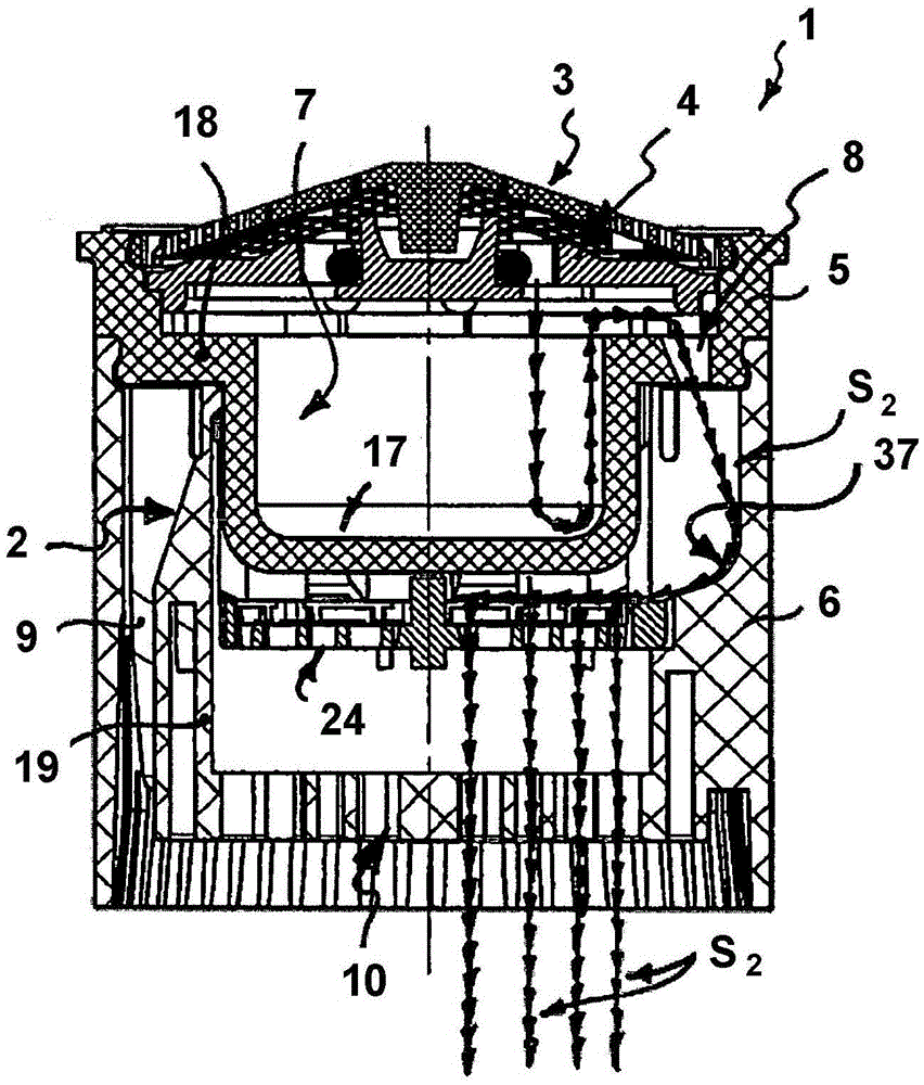
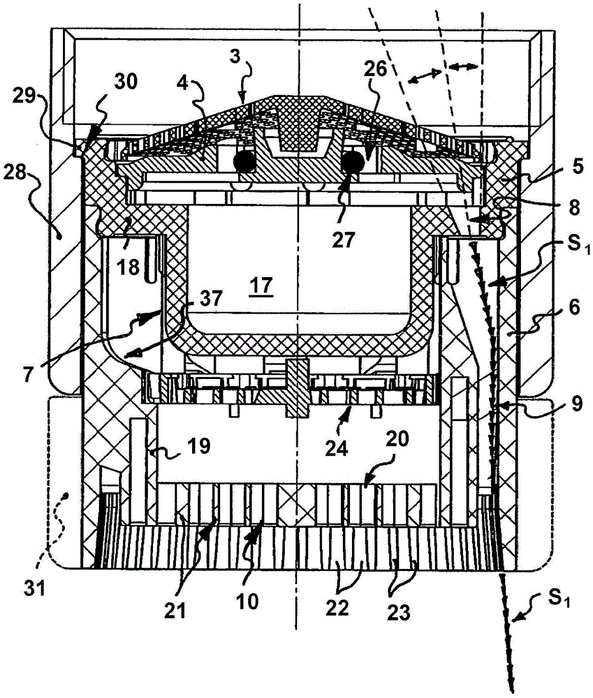
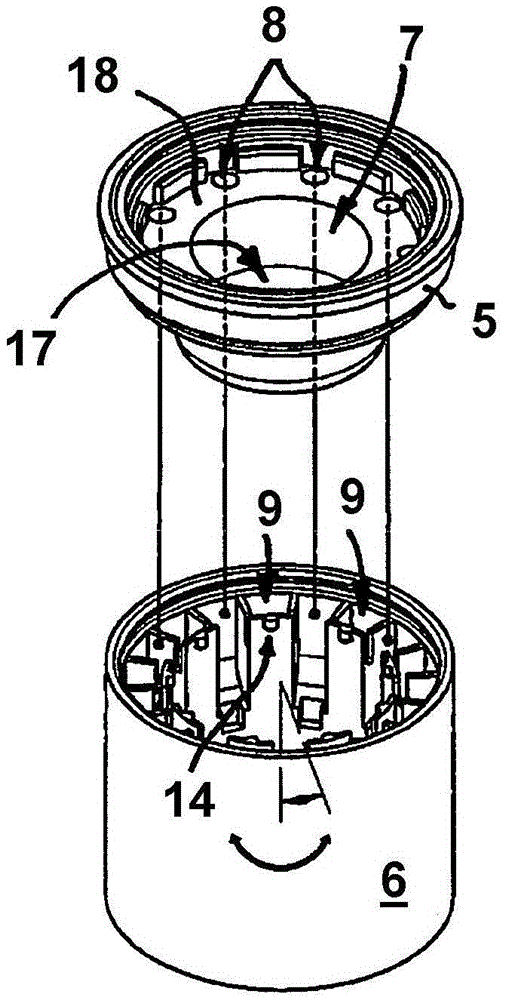
[0084] exist Figures 1 to 29 Two implementations 1, 1' of the built-in unit for hygiene are shown in . as in figure 2 As shown in the example, the built-in unit 1, 1' can be assembled by means of an outflow connection part 28 on the water outlet of a sanitary water tap not shown further here. The built-in unit 1, 1' has a jet regulator 2, 2' on the outflow side, which can be selectively switched between two outflow jet patterns (see figure 1 , 2 as well as Figure 24 , 25 ) to switch between. The built-in unit 1, 1' has an inflow-side pre-sieve or filter sieve 3, 3' which is able to filter calcium salt particles or dirt particles contained in the inflow water Otherwise, the calcium salt particles or dirt particles would otherwise be fixed in the built-in unit 1, 1' and interfere with its function. In order to be able to adjust the amount of water flowing through the built-in unit 1, 1' per unit time to a fixed maximum value independently of the pressure, between the p...


PUM


Abstract

The invention relates to a jet regulator which has a jet regulator housing with at least two housing parts which can be rotated relative to each other. An inflow-side first housing part of the two housing parts can be mounted on the water outlet of a sanitary outlet fitting in a rotationally fixed manner, and an outflow-side second housing part of the two housing parts is designed as a handle at least on the outer circumference or is connected to a handle. The first housing part is designed as a jet divider with multiple divider openings, and mutually spaced jet channels are provided on the housing inner circumference of the second housing part. Individual jets coming from the divider openings are guided through the jet channels and shaped into an annularly circumferential outlet jet pattern in a first rotational position of the housing parts and deflected in the housing interior of the jet regulator to a central outlet opening of the jet regulator housing in a second rotational position. The jet regulator is characterized in that a rotational latch with at least one latching mechanism is provided, wherein the latching mechanism is molded on a channel wall facing the housing interior of the jet regulator housing, and the latching mechanism interacts with a profiled latching section, and in that a grid or net structure which extends over the central outlet opening is integrally molded on the second housing part on the outflow side.

Description

technical field [0001] The invention relates to a jet regulator which can be switched selectively between at least two outflow jet patterns and which has a jet regulator comprising at least two housing parts which are rotatable relative to each other. Among these housing parts, the first housing part on the inflow side can be assembled on the water outlet of the sanitary water faucet in a relatively non-rotatable manner, and the second housing part on the outflow side among these housing parts At least on its outflow-side housing outer circumference, it is formed as a handle or is connected to the handle, the first housing part has a jet splitter with a plurality of disintegrating openings, and the housing inner circumference of the second housing part is provided with mutual Jet channels spaced apart, through which the individual jets exiting the disintegration opening are guided in the first rotational position of the housing part and form a circularly encircling outflow jet...

Claims


Application Information

Patent Timeline
IPC IPC(8): E03C1/08
CPCE03C1/08E03C1/084B05B1/1654B05B7/04B05B7/0425
Inventor D·比尔梅林
Owner NEOPERL
Why Eureka
Eureka Blog
Learn More