Novel multi-rotor unmanned aerial vehicle

A multi-rotor UAV, a new type of technology, applied in the field of aircraft, can solve the problems of single energy supply mode, large body damage, troublesome battery replacement, etc., and achieve the effect of good fixed balance, extended battery life, and quick and convenient replacement

Inactive Publication Date: 2016-09-21
大理铂骏科技有限公司
View PDF10 Cites 8 Cited by
  • Summary
  • Abstract
  • Description
  • Claims
  • Application Information

AI Technical Summary

Problems solved by technology

[0005] (2) The fixing position of the battery is inconvenient. At present, multi-rotor UAVs usually use straps to directly bind the battery to the lower end of the frame. It is determined that it directly affects the flight balance of the multi-rotor UAV, and it is not safe;
[0006] (3) It is troublesome to replace the battery. At present, the replacement of the multi-rotor UAV battery is performed manually, which largely takes up the time of the flight operator;
[0007] (4) The energy supply method is single, and the existing multi-rotor drones mostly use lithium batteries for power supply;
[0008] (5) The landing shock absorption effect is poor. At present, most multi-rotor UAVs achieve the effect of landing shock absorption by setting sharp-edged flexible materials at the lower end of the frame propeller. Great damage to the body

Method used


Image

  • Novel multi-rotor unmanned aerial vehicle
  • Novel multi-rotor unmanned aerial vehicle
  • Novel multi-rotor unmanned aerial vehicle

Examples


Embodiment Construction

[0037]In order to make the technical means, creative features, goals and effects achieved by the present invention easy to understand, the present invention will be further described below in conjunction with specific illustrations.

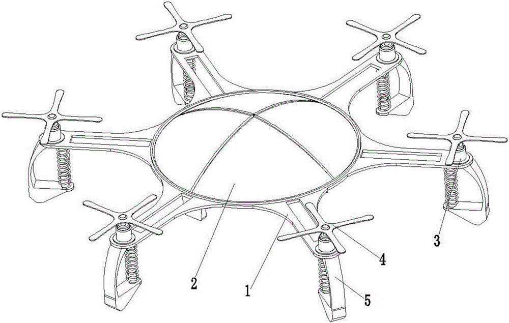
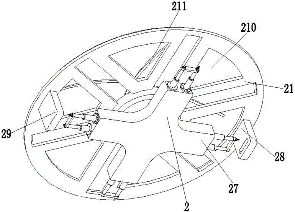
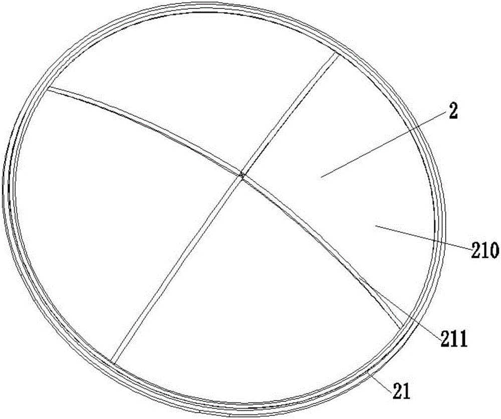
[0038] Such as Figure 1 to Figure 9 As shown, a novel multi-rotor UAV includes a frame 1, an energy supply device 2, a motor 3, a propeller 4 and a shock absorber 5; There are six brackets evenly and symmetrically arranged on the central axis, and the frame 1 is made of carbon fiber material at one time. The carbon fiber material has high axial strength and modulus, low density, high specific performance, no creep, ultra-high temperature resistance and Light weight and other advantages, the frame 1 made of carbon fiber material is light in quality, and a strip-shaped material reduction port is opened on the bracket; the energy supply device 2 is located in the middle of the frame 1; the motor 3, propeller 4 and reduction The number of vibration...


PUM


Abstract

The invention relates to a novel multi-rotor unmanned aerial vehicle. The novel multi-rotor unmanned aerial vehicle comprises a rack, an energy supplying device, motors, propellers and shock absorbing seats. The energy supplying device is located in the middle of the rack. The motors are installed on the top end faces of six supports correspondingly. The propellers are fixed to spindles of the motors correspondingly. The shock absorbing seats are located on the bottom end faces of the six supports correspondingly. The shock absorbing seats are adopted for the novel multi-rotor unmanned aerial vehicle, so that vibration generated between an unmanned aerial vehicle body and the ground duding landing of the novel multi-rotor unmanned aerial vehicle is reduced, thus damage to the unmanned aerial vehicle body duding landing of the novel multi-rotor unmanned aerial vehicle is reduced to a certain extent, and the shock absorbing effect is good. In addition, in the flying process, solar energy can be converted into electric energy through solar cell panels, and power is supplied to the novel multi-rotor unmanned aerial vehicle directly, so that duration of flight of the novel multi-rotor unmanned aerial vehicle is prolonged. Meanwhile, the function of automatic in-turn replacement of batteries is achieved through battery allocation devices, manual replacement is not needed, replacement is fast and convenient, the batteries are good in fixation balance and high in safety.

Description

technical field [0001] The invention relates to the field of aircraft, in particular to a novel multi-rotor unmanned aerial vehicle. Background technique [0002] UAV is an unmanned aircraft controlled by radio remote control equipment and self-contained program control device. From a technical point of view, it can be divided into unmanned helicopter, unmanned fixed-wing aircraft, unmanned multi-rotor aircraft, unmanned airship and unmanned aircraft. UAVs can be divided into military and civilian use according to the application field, and military UAVs are divided into reconnaissance aircraft and target drones; at present, UAVs can be widely used in national ecological environment protection, aerial photography, surveying and mapping, mineral resources Exploration, disaster monitoring, traffic patrol, power line inspection, public security monitoring, emergency disaster reduction, emergency command, artificial rainfall, national defense security, land and resource explorat...

Claims


Application Information

Patent Timeline
Patent Type & Authority Applications(China)
IPC IPC(8): B64C27/08B64C25/62
CPCB64C25/62B64C27/08B64D2211/00B64U50/19B64U10/10
Inventor 郑琳琳
Owner 大理铂骏科技有限公司
Why Eureka
Try Eureka