Drill bit, drilling tool and local underbalanced drilling method
A drill bit and drilling fluid technology, applied in wellbore/well components, earthwork drilling, wellbore flushing, etc., can solve problems such as unusable high-pressure and high-permeability formations, stuck drill, downhole explosion, etc., and achieve wellbore out of control Low risk, increased ROP, and wellbore stability
- Summary
- Abstract
- Description
- Claims
- Application Information
AI Technical Summary
Problems solved by technology
Method used
Image
Examples
Embodiment 1
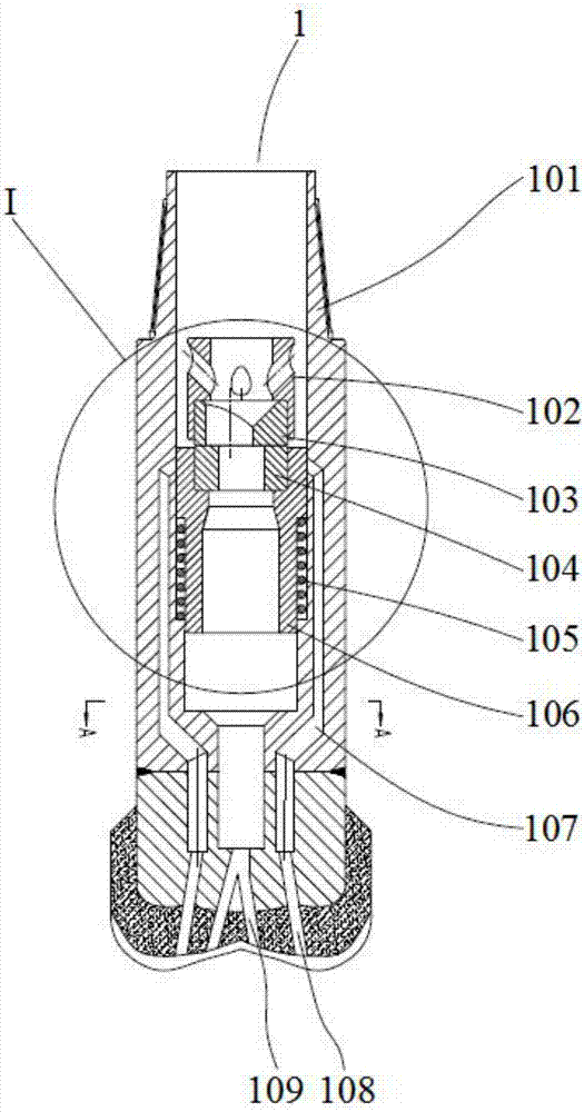
[0067] This embodiment relates to a drill bit 1, comprising a housing 101, a plurality of high-pressure nozzles 108 and at least one water eye nozzle 109 are arranged at the bottom of the housing 101, and a plurality of high-pressure nozzles 108 are arranged in a ring and each of the water eye nozzles 109 is surrounded inside; the housing 101 is provided with:
[0068] A bypass channel mechanism for delivering drilling fluid to each of the high-pressure nozzles 108;
[0069] An intermediate channel mechanism for delivering drilling fluid to each of the water eye nozzles 109;
[0070] A pressurization mechanism for periodically causing the drilling fluid entering the inner cavity of the casing 101 to generate water hammer pressurization;
[0071] A flow channel control mechanism for introducing drilling fluid pressurized to a preset pressure by the booster mechanism into the bypass flow channel mechanism and drilling fluid with a pressure lower than the preset pressure into th...
Embodiment 2
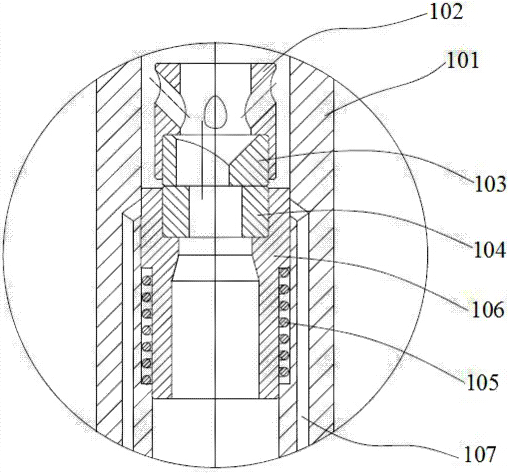
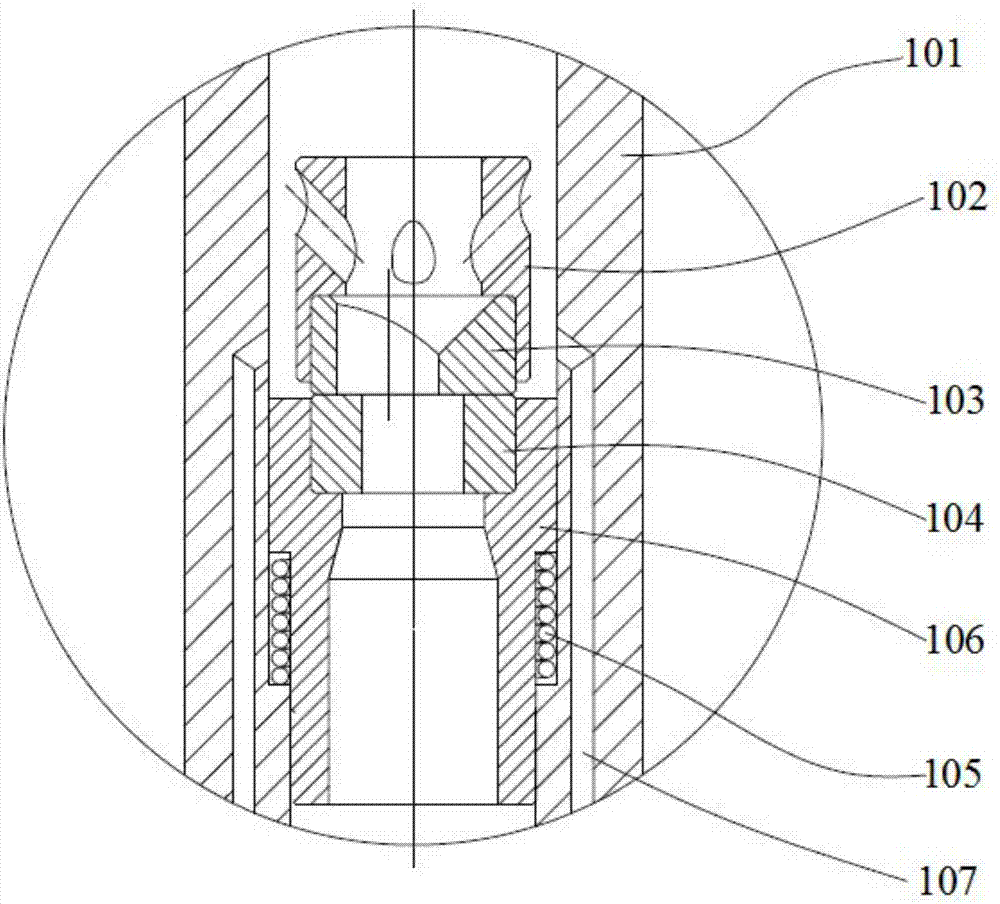
[0077] Such as Figure 1-Figure 5 , The embodiment of the present invention provides a drill bit, including a housing 101 , and the inner cavity of the housing 101 is provided with a water connection 102 , an upper valve plate 103 , a lower valve plate 104 , a lower valve seat 106 and a reset mechanism 105 . The water joint 102 adopts the water joint commonly used in drilling tools, and its central axis coincides with the central axis of the housing 101. It has an inner cavity and an open lower end, and its outer diameter is smaller than the inner diameter of the housing 101. An annular space is formed between the bodies 101 for the circulation of drilling fluid, and the drilling fluid can enter the inner cavity of the water connection 102 through a plurality of water holes provided on the water connection 102 . The lower valve seat is located below the water connection 102, which includes a plunger 106 embedded in the inner cavity of the housing 101, that is, the outer diamet...
Embodiment 3
[0088] Such as Image 6 , the embodiment of the present invention provides a drill bit 1 whose structure is basically the same as that of the drill bit 1 provided in the second embodiment, except for the structure of the lower valve seat 106 . In this embodiment, the lower valve seat 106 is fixedly connected to the inner cavity of the housing 101, and the fixed connection method is preferably a screw connection, so as to facilitate disassembly, replacement and maintenance; The flow channel communicates with each water eye nozzle 109 ; the bypass flow channel mechanism 107 is arranged in the wall of the housing 101 , and its inlet end is located above the lower valve seat 106 and communicates with the inner cavity of the housing 101 .
[0089] In this embodiment, the bypass channel mechanism 107 is in a normally open state, and the above-mentioned lower valve seat 106 and the lower valve plate 104 constitute the above-mentioned flow channel control mechanism. In the initial st...
PUM
 Abstract
Description
Claims
Application Information
 - R&D
- Intellectual Property
- Life Sciences
- Materials
- Tech Scout
- Unparalleled Data Quality
- Higher Quality Content
- 60% Fewer Hallucinations
Browse by: Latest US Patents, China's latest patents, Technical Efficacy Thesaurus, Application Domain, Technology Topic, Popular Technical Reports.
© 2025 PatSnap. All rights reserved.Legal|Privacy policy|Modern Slavery Act Transparency Statement|Sitemap|About US| Contact US: help@patsnap.com


