Electric energy metering method
A technology of electric energy measurement and electric energy measurement system, applied in the field of electric energy measurement, can solve problems such as poor electric energy accuracy, and achieve the effects of strong measurement accuracy, simple structure and less hardware resources
- Summary
- Abstract
- Description
- Claims
- Application Information
AI Technical Summary
Problems solved by technology
Method used
Image
Examples
specific Embodiment approach 1
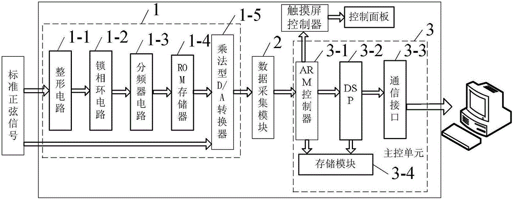
[0038] Specific implementation mode one: refer to picture 1 Describe this embodiment in detail, the A method of measuring electric energy , which is realized based on an electric energy metering system. An electric energy metering system includes a housing, a control panel, input terminals, output terminals, a power supply, a touch screen controller, an analog signal generator 1, a data acquisition module 2 and a main control Unit 3,
[0039] The power supply, touch screen controller, analog signal generator 1, data acquisition module 2 and main control unit 3 are all installed in the housing, and the control panel, input terminals and output terminals are all on the upper surface of the housing.
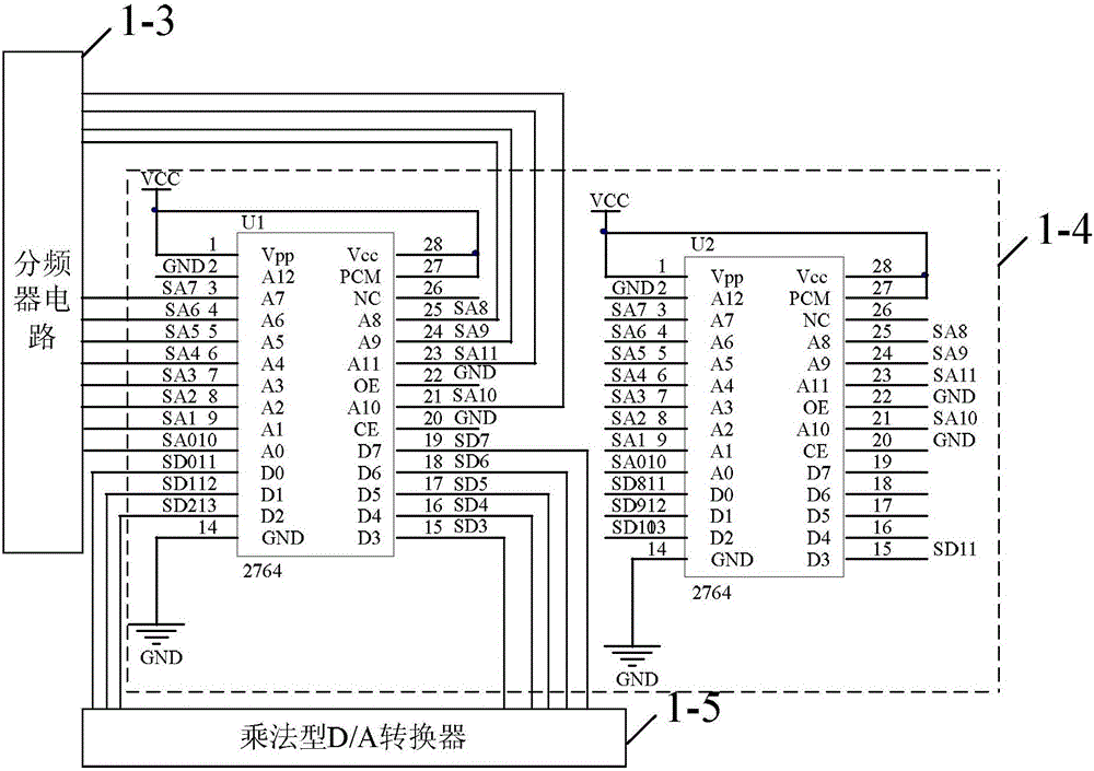
[0040] The analog signal generator 1 comprises a shaping circuit 1-1, a phase-locked loop circuit 1-2, a frequency divider circuit 1-3, a ROM memory 1-4 and a multiplication type D / A converter 1-5,
[0041] Main control unit 3 comprises ARM controller 3-1, DSP3-2 and communicat...
specific Embodiment approach 2
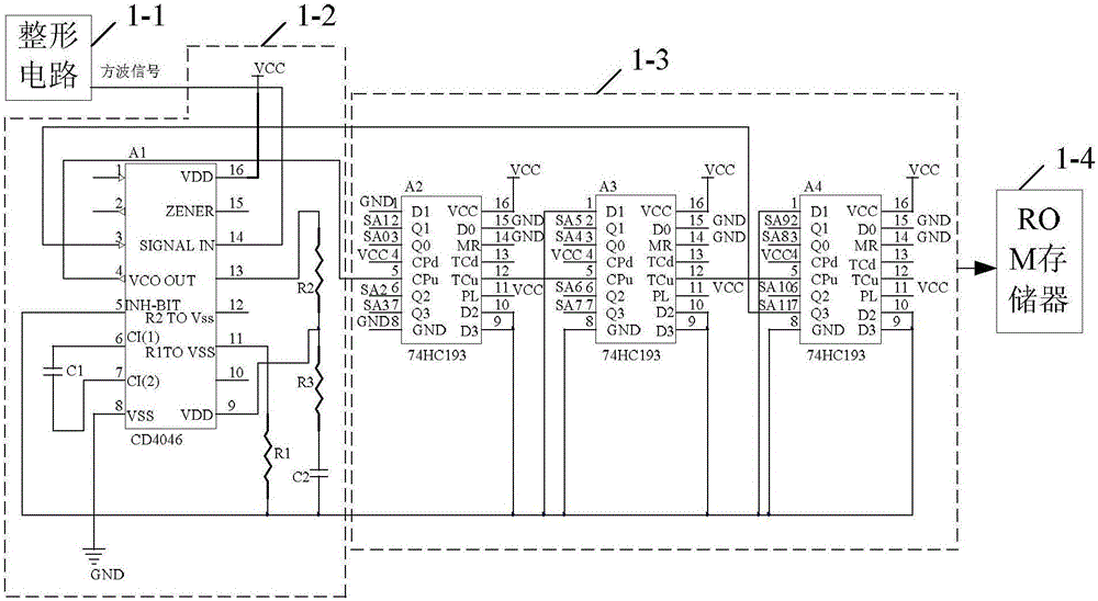
[0063] Specific implementation mode two: refer to picture 2 This implementation mode is described in detail, and this implementation mode is described in the first specific implementation mode A method of measuring electric energy For further explanation, in this embodiment, the phase-locked loop circuit 1-2 includes a CMOS phase-locked loop integrated chip A1 whose model is CD4046, a resistor R1, a resistor R2, a resistor R3, a capacitor C1 and a capacitor C2,
[0064] The frequency divider circuit 1-3 includes the synchronous reversible counter A2 of No. 1 model 74HC193, the synchronous reversible counter A3 of No. 2 model 74HC193 and the synchronous reversible counter A4 of No. 3 model 74HC193,
[0065] The No. 14 pin of the CMOS phase-locked loop integrated chip A1 whose model is CD4046 is connected to the shaping signal output terminal of the shaping circuit 1-1,
[0066] The No. 6 pin of the CMOS phase-locked loop integrated chip A1 whose model is CD4046 is connected...
specific Embodiment approach 3
[0074] Specific implementation mode three: refer to picture 4 This implementation mode is described in detail, and this implementation mode is described in the first specific implementation mode A method of measuring electric energy For further explanation, in the present embodiment, the multiplying D / A converter 1-5 comprises the multiplying digital-to-analog conversion chip that the model is AD7845, resistor R4, resistor R5 and operational amplifier OP,
[0075] The No. 2 to No. 14 pins of the AD7845 multiplication digital-to-analog conversion chip are connected to the buffer signal output terminals of the ROM memory 1-4,
[0076] The 12th and 18th pins of the AD7845 multiplying digital-to-analog conversion chip are connected to the power ground,
[0077] The No. 1 pin and the No. 23 pin of the multiplication digital-to-analog conversion chip whose model is AD7845 are connected to the conversion signal input end of the data acquisition module 2,
[0078] The No. 22 pin ...
PUM
 Abstract
Description
Claims
Application Information
 - R&D
- Intellectual Property
- Life Sciences
- Materials
- Tech Scout
- Unparalleled Data Quality
- Higher Quality Content
- 60% Fewer Hallucinations
Browse by: Latest US Patents, China's latest patents, Technical Efficacy Thesaurus, Application Domain, Technology Topic, Popular Technical Reports.
© 2025 PatSnap. All rights reserved.Legal|Privacy policy|Modern Slavery Act Transparency Statement|Sitemap|About US| Contact US: help@patsnap.com


