
Fault arc detection method and detection apparatus

A detection method and fault arc technology, which are applied in the direction of measuring devices, measuring electricity, measuring electrical variables, etc., can solve the problems of threshold setting relying on experience and data, false alarms, and difficulty in coordination.

Active Publication Date: 2016-09-21
SHENZHEN CITY ZHI SHENGAN SECURITY TECH
View PDF6 Cites 15 Cited by
  • Summary
  • Abstract
  • Description
  • Claims
  • Application Information

AI Technical Summary

Problems solved by technology

There are many methods for detecting arc faults in the power grid, and some algorithms require too many thresholds, which are difficult to coordinate; the setting of thresholds depends heavily on experience and data, and is difficult to promote
In some methods, the initial normal waveform data needs to be input in advance. If the load is different, it may be falsely reported; the normal waveform data is updated dynamically. If the waveform does not exceed the threshold every time it is updated, it will be accumulated multiple times. Under this condition, the data of the normal waveform will no longer be normal, making it impossible to detect
It also requires multiple thresholds, depends on data and experience, and is difficult to promote
In some methods, the typical value of the high-order harmonic content rate will be updated dynamically. If there is a change that does not exceed the threshold value in each update, the typical value will no longer be normal after multiple accumulations, so it cannot be detected.
The criterion is too single, and it is easy to misdetect only relying on the detection of high-order harmonics
For some methods, when the load power is small, it cannot be detected

Method used


Image

  • Fault arc detection method and detection apparatus
  • Fault arc detection method and detection apparatus
  • Fault arc detection method and detection apparatus

Examples


Embodiment Construction

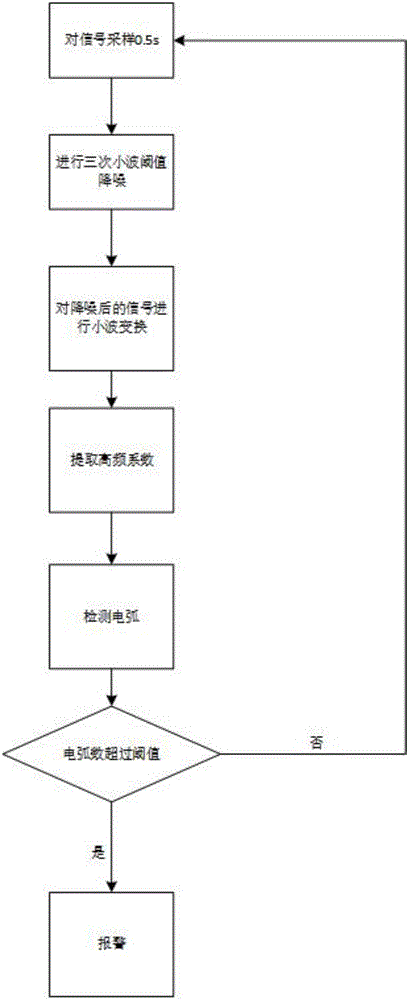
[0065] Embodiment of the arc fault detection method of the present invention:

[0066] Step 1: Use the analog-to-digital conversion interface of the STM32 microcontroller to collect circuit signals;

[0067] Step 2: Determine whether the number of sampling points reaches the preset value of the number of sampling points within 0.5s, if so, proceed to the next step, otherwise proceed to step 1;

[0068] Step 3: Use DB4 wavelet to perform wavelet threshold noise reduction on the collected signal, a total of three times;

[0069] Step 4: Carry out two-layer wavelet transform on the signal after noise reduction;

[0070] Step 5: extracting the second layer high-frequency coefficients (detail coefficients);

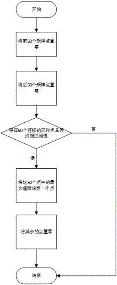
[0071] Step 6: processing high-frequency coefficients (detail coefficients);

[0072] Step 7: Count the number of points that are not 0 in the high-frequency coefficients after statistical processing;

[0073] Step 8: If the statistical value is greater than the preset thres...


PUM


Abstract

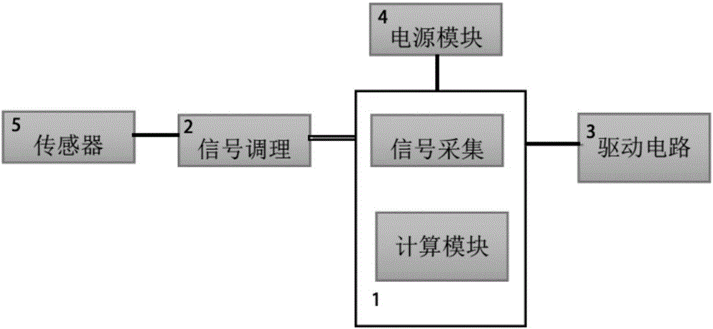
The invention discloses a fault arc detection method and detection apparatus, and relates to detection of electrical faults. The method comprises the following steps: acquiring circuit signals; determining whether an acquisition point quantity reaches a preset value of an acquisition point quantity within 0.5 s, if so, performing the next step, and otherwise, returning; performing wavelet threshold noise reduction on the acquired signals by use of DB4 wavelets; performing two-layer wavelet transformation on the signals after the noise reduction; extracting a second-layer high-frequency coefficient; processing the second-layer high-frequency coefficient; counting the quantity of points which are not zero in the processed second-layer high-frequency coefficient; and if a statistical value is greater than a preset threshold, giving an alarm, and otherwise, returning to the first step. A single-chip microcomputer module is connected with a signal conditioning module, a driving module and a power supply module, the signal conditioning module is connected with a sensor module, and the single-chip microcomputer module comprises a signal acquisition module and a calculation module. According to the invention, the purposes of improving fault arc detection precision, reducing the false alarm rate and improving the detection accuracy are realized.

Description

technical field [0001] The invention relates to a detection device for electrical faults, in particular to detection of faults in cables, transmission lines or networks, in particular to a fault arc detection method and detection device. Background technique [0002] Fault arc detection technology is to convert harmful arc pulses (such as arcs caused by wire insulation drop, load short circuit, and poor contact of switch connectors) that are prone to electrical fires from a large number of harmless arc pulses (such as energy-saving , electric hair dryer, electric hand drill, vacuum cleaner, arc welding machine, air compressor, high-power switch action, etc.) and interference pulses are detected, and then the power is cut off without malfunctioning. There are many methods for detecting arc faults in the power grid, and some algorithms require too many thresholds, which are difficult to coordinate; the setting of thresholds depends heavily on experience and data, and is diffic...

Claims


Application Information

Patent Timeline
IPC IPC(8): G01R31/00G01R31/02G01R31/12
CPCG01R31/00G01R31/1272G01R31/50
Inventor 邵景莅陈霸东荣涛黄大维蒋伟平
Owner SHENZHEN CITY ZHI SHENGAN SECURITY TECH
Learn More