
Crystal oscillator and production method thereof

A crystal oscillator and chip technology, which is applied in the electronic field, can solve the problems of mobile phone timing disorder, chip conductive upper cover collision and short circuit, etc., and achieve the effect of preventing mobile phone timing disorder, preventing short circuit to ground, and simple method

Inactive Publication Date: 2016-09-21
VIVO MOBILE COMM CO LTD
View PDF10 Cites 0 Cited by
  • Summary
  • Abstract
  • Description
  • Claims
  • Application Information

AI Technical Summary

Problems solved by technology

[0004] In order to overcome the problem in the prior art that the chip is easy to collide with the conductive upper cover and short circuit during the process of falling and rolling, the embodiment of the present invention provides a crystal oscillator and its production method, which can effectively insulate the wafer and the conductive upper cover. , to prevent the chip from colliding with the conductive upper cover to cause a short circuit to the ground, which will lead to bad phenomena such as disordered timing of the mobile phone

Method used


Image

  • Crystal oscillator and production method thereof
  • Crystal oscillator and production method thereof
  • Crystal oscillator and production method thereof

Examples


Embodiment 1

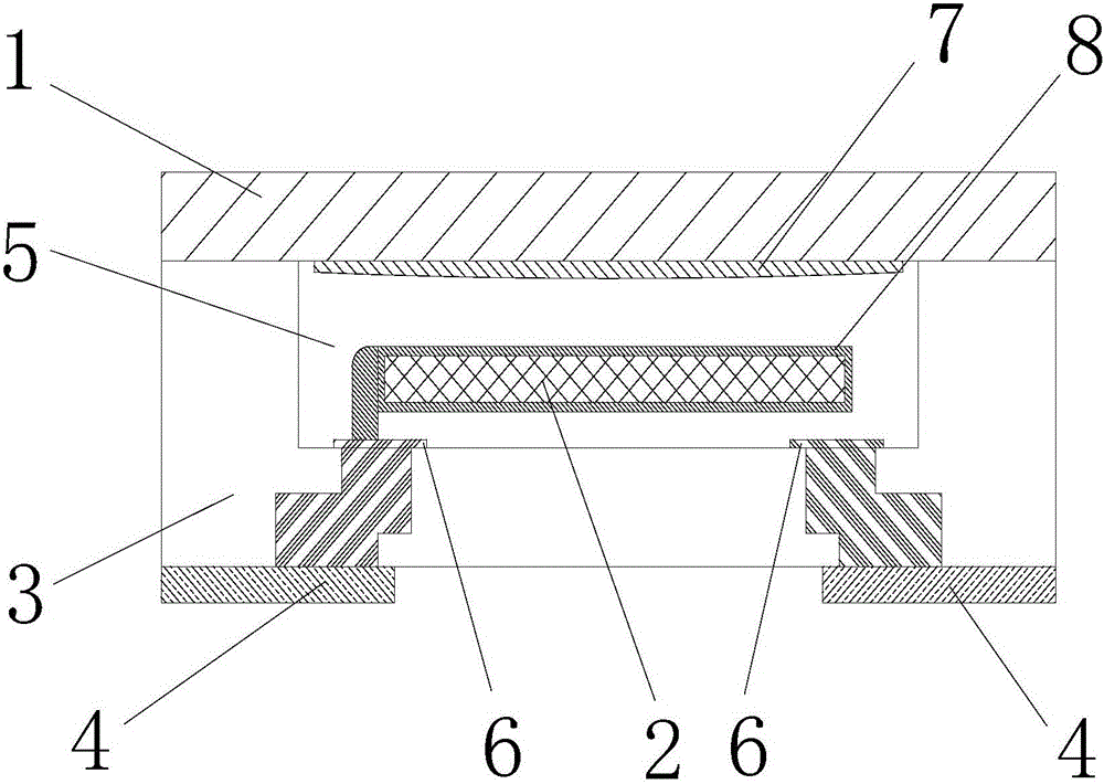
[0035] figure 2 It is a schematic diagram of the structure of a crystal oscillator provided by an embodiment of the present invention, such as figure 2 As shown, a crystal oscillator provided by the present invention includes a base 3, a conductive upper cover provided on the top of the base 3, a chip 2 provided in the base 3, and two pads 4 provided at the bottom of the base 3 The base 3 is provided with an accommodation cavity 5 under the conductive upper cover 1, two connection solder joints 6 are provided at the bottom of the accommodation cavity 5 to be connected to the pad 4 correspondingly, and the chip 2 is provided in the accommodation In the cavity 5, an electrode 8 is provided on the surface of the chip 2 to be connected to one of the connection solder joints 6, wherein the bottom surface of the conductive upper cover 1 is provided with a preset position 7 above the chip 2. An insulating layer is provided on it. The insulating layer at the preset position 7 insulat...

Embodiment 2

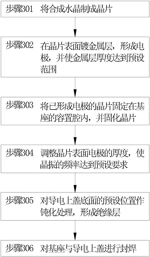
[0038] image 3 Is a schematic flow chart of a crystal oscillator manufacturing method provided by an embodiment of the present invention; Figure 4 It is a schematic flow diagram of the step of forming a synthetic crystal into a wafer in the crystal oscillator manufacturing method provided by an embodiment of the present invention.

[0039] Such as figure 2 As shown, the method for manufacturing a crystal oscillator provided by the present invention includes:

[0040] Step 301: The synthetic crystal is made into a chip 2;

[0041] In step 302, a metal layer is plated on the surface of the wafer 2 to form an electrode 8 and the thickness of the metal layer reaches a preset range;

[0042] Step 303: Fix the wafer 2 with the electrode 8 formed in the accommodating cavity 5 of the base 3, and solidify the wafer 2;

[0043] Step 304 adjust the thickness of the electrode 8 on the surface of the wafer 2 so that the frequency of the crystal oscillator meets the preset requirement;

[0044] St...


PUM


Abstract

The invention provides a crystal oscillator and a production method thereof. The crystal oscillator comprises a base, a conductive upper cover arranged on the top of the base, a crystal plate arranged in the base and two pads arranged at the bottom of the base. The base is equipped with a containing cavity located under the conductive upper cover. Two connection welding spots arranged at the bottom of the containing cavity are correspondingly connected with the pads. The crystal plate is arranged in the containing cavity. An electrode arranged on the surface of the crystal plate is connected with one of the connection welding spots. A preset position is arranged on the bottom surface of the conductive upper cover and is located above the crystal plate. Insulation paint is coated at the preset position. Through adoption of the insulation paint at the preset position, the crystal plate and the conductive upper cover are insulated; the method is simple; and the bad problems such as disordered time sequence of a mobile phone due to the short circuit over the ground are effectively solved. The short circuit over the ground results from collision of the crystal plate and the conductive upper cover in the fall-off and rolling processes.

Description

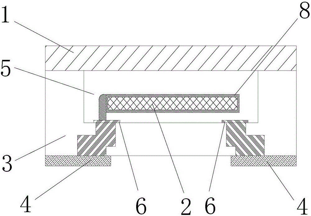
Technical field [0001] The invention relates to the field of electronics, in particular to a crystal oscillator and its manufacturing method. Background technique [0002] Crystal oscillator is the collective name of quartz crystal resonator and quartz crystal oscillator. It is made of quartz crystal with piezoelectric effect. Its function is to generate the original clock frequency, which is different after being amplified or reduced by different frequency generators. Bus frequency. Because the crystal oscillator has the advantages of small size, light weight, high reliability, and high frequency stability, it is used in consumer electronics such as mobile phones and pads. [0003] The current crystal structure is as figure 1 As shown, it includes a pedestal, a conductive upper cover arranged on the top of the pedestal, a chip arranged in the pedestal, and two pads arranged on the bottom of the pedestal. The pedestal is provided with a receiving cavity under the conductive upper ...

Claims


Application Information

Patent Timeline
IPC IPC(8): H03H3/02H03H9/19
CPCH03H3/02H03H9/19
Inventor 孙学彪吉圣平李明周伟杰羿冬冬
Owner VIVO MOBILE COMM CO LTD
Learn More