An Automatically Controlled Tailstock Feeding Method of CNC Lathe

A CNC lathe tailstock and CNC lathe technology, applied in the field of CNC lathes, can solve the problems of low processing efficiency, time-consuming and laborious, and the tailstock cannot be automatically fed, and achieve the effect of expanding functions and improving the degree of automation

Active Publication Date: 2017-12-08
惠州合友五金制品有限公司
View PDF6 Cites 0 Cited by
  • Summary
  • Abstract
  • Description
  • Claims
  • Application Information

AI Technical Summary

Problems solved by technology

[0002] CNC lathes are one of the most commonly used automatic processing equipment in mechanical cutting. However, the tailstock of general CNC machine tools cannot be automatically fed, and can only be operated manually, which is time-consuming and laborious, and the processing efficiency is low. Dimensional control accuracy is low

Method used


Image

  • An Automatically Controlled Tailstock Feeding Method of CNC Lathe
  • An Automatically Controlled Tailstock Feeding Method of CNC Lathe
  • An Automatically Controlled Tailstock Feeding Method of CNC Lathe

Examples


Embodiment Construction

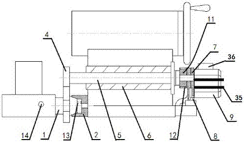
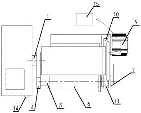
[0015] An automatically controlled CNC lathe tailstock feeding method, which uses a CNC lathe saddle and a tailstock coupling and disengagement connection device, including a centering assembly, a rotating arm assembly and a drive assembly. The centering The assembly includes a pair of center shafts 1 and a centering sleeve 2 with an inner tapered hole. A ring groove 3 is provided in the middle of the centering shaft 1. The centering shaft 1 is fixedly connected with the saddle of the CNC lathe, and the centering sleeve 2 is connected to the end of the CNC lathe. The base is fixedly connected, the front end of the centering shaft 1 and the inner taper hole of the centering sleeve 2 form a conical surface fit. The shaft end of the centering shaft 1 and the bottom of the taper hole of the centering sleeve 2 are provided with a sensor 13 which can be Magnetic effect sensor or Hall effect sensor, or photoelectric sensor;

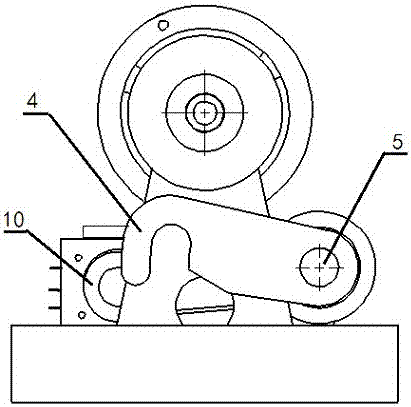
[0016] The rotating arm assembly includes a rotating arm 4, a...


PUM


Abstract

The invention provides an automatically-controlled numerically controlled lathe tailstock feeding method. A connecting device which combines a numerically controlled lathe saddle and a tailstock and disengages the numerically controlled lathe saddle from the tailstock is adopted. The connecting device comprises an alignment assembly, a rotating arm assembly and a driving assembly; the alignment assembly comprises an alignment shaft (1) and an alignment sleeve (2) with an inner cone hole, a sensor (13) is arranged at the shaft end of the alignment shaft (1) and at the bottom of the cone hole of the alignment sleeve (2); the rotating arm assembly comprises a rotating arm (4), a rotating shaft (5), a shaft sleeve (6) and two limiting pressing blocks (7); the driving assembly comprises a pair of belt drives, a driving motor (9), a reset switch (14) and a controller (15); the controller (15) is installed in a machine tool power distribution cabinet, the reset switch (14) is installed in front of the numerically controlled lathe saddle and electrically connected with the controller, the driving motor (9) is fixedly connected with the tailstock of the numerically controlled lathe and electrically connected with the controller (15), and a vibration reduction backing plate is arranged between the driving motor (9) and the tailstock of the numerically controlled lathe and used for reducing vibratory force generated when the driving motor (9) operates.

Description

Technical field [0001] This application relates to the technical field of numerical control lathes, and specifically is an automatic control method for feeding the tailstock of a numerical control lathe. Background technique [0002] CNC lathe is one of the most commonly used automatic processing equipment in mechanical cutting. However, the tailstock of general CNC machine tools cannot be automatically fed and can only be operated manually, which is time-consuming and labor-intensive, and has low processing efficiency. The dimensional control accuracy is low. Summary of the invention [0003] In view of the existing technical defects, the present invention provides an automatically controlled CNC lathe tailstock feeding method, which uses a CNC lathe saddle and a tailstock coupling and disengagement connection device, and its structure is simple, The control is easy, the cost is low, the function of the CNC lathe is expanded, and the machining accuracy of the axial dimension of ...

Claims


Application Information

Patent Timeline
Patent Type & Authority Patents(China)
IPC IPC(8): B23Q5/34B23B23/00
CPCB23B23/00B23Q5/34
Inventor 冯淑珠
Owner 惠州合友五金制品有限公司
Why Eureka
Try Eureka