
Additive manufacturing system capable of achieving rapid deposition on surface of workpiece through vacuum plasma

A workpiece surface and plasma technology, which is applied in the field of rapid formation of high-performance thick coatings and additive manufacturing systems, can solve the problems of poor deposition coating effect on complex workpieces, low coating deposition efficiency, and thin coating thickness. Achieve the effects of reducing the chance of stripping, increasing the binding force, and increasing the adhesion

Active Publication Date: 2016-09-28
GUANGDONG STRONG METAL TECH
View PDF6 Cites 4 Cited by
  • Summary
  • Abstract
  • Description
  • Claims
  • Application Information

AI Technical Summary

Problems solved by technology

[0004] The purpose of the present invention is to solve the problems of low coating deposition efficiency on the workpiece surface, thin and uneven deposited coating thickness, and poor deposition coating effect on complex workpieces in the prior art re-coating additive manufacturing system. An Additive Manufacturing System for Rapid Deposition on Workpiece Surfaces by Vacuum Plasma

Method used


Image

  • Additive manufacturing system capable of achieving rapid deposition on surface of workpiece through vacuum plasma
  • Additive manufacturing system capable of achieving rapid deposition on surface of workpiece through vacuum plasma
  • Additive manufacturing system capable of achieving rapid deposition on surface of workpiece through vacuum plasma

Examples


specific Embodiment 1

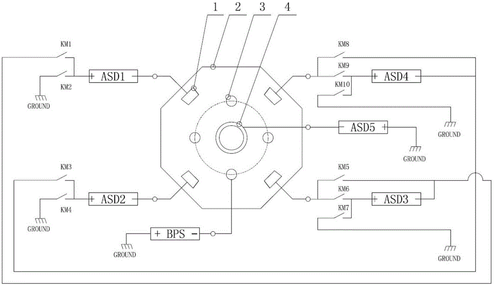
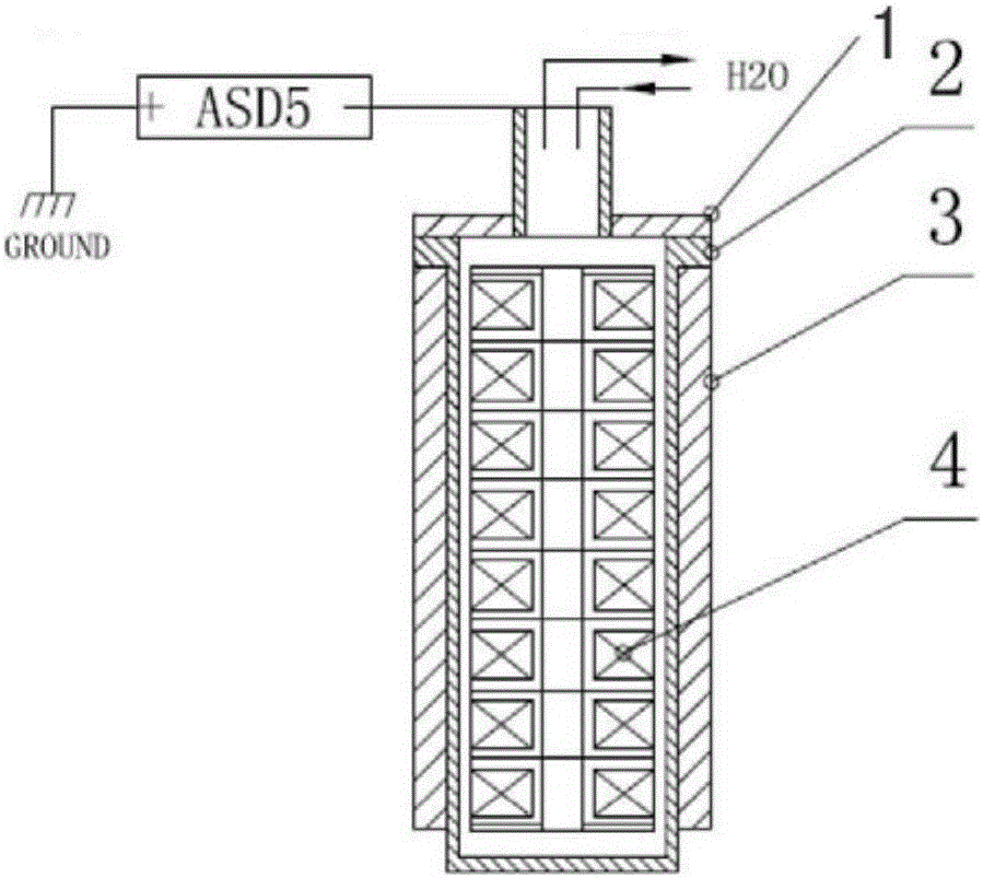
[0038] refer to Figure 1 to Figure 5 , the present embodiment includes a vacuum obtaining and measuring device 1 and a vacuum chamber 10, the vacuum obtaining and measuring device 1 communicates with the vacuum chamber 10 through a vacuum pipeline 2, and a plurality of side wall cathode target pairs are installed on the side wall of the vacuum chamber 10, A columnar cathode target 4 and a rotary support mechanism 3 are installed in the center of the vacuum chamber 10. The columnar cathode target 4 has a high-power and high-current structure. The columnar cathode target 4 is connected to a high-power arc power supply to output a large current. The columnar cathode target The power input terminal of 4 is connected to the output terminal of the PLC control system, and the positive and negative input switches are repeatedly performed through the PLC control system to change the direction of the electromagnetic field acting on the target surface of the columnar cathode target 4, so...

specific Embodiment 2

[0072] The characteristics of this embodiment 2 are: the vacuum chamber 10 is an equilateral octagon with eight rectangular surfaces, one of which is connected to the vacuum obtaining system and its measuring device 1 through the vacuum pipeline 2, and the other seven rectangular surfaces have rectangular openings 1. It is used to connect the rectangular flange. A cathode target 23 is installed on each of the six rectangular flanges. The cathode target 23 is externally connected with a cathode arc power input device 24 and a cooling water inlet and outlet device 25. The cathode target 23 An electromagnetic field 22 is provided around the , forming three pairs of sidewall cathode targets. All the other are with specific embodiment 1.

specific Embodiment 3

[0073] refer to Figure 6 to Figure 8 , the feature of the specific embodiment 4 of the present invention is that the structure of the vacuum chamber 10 can be circular, and four to eight windows are formed on the circumference, one of which is connected to the vacuum obtaining system and its measuring device 1 through the vacuum pipeline 2, and the other three to The seven windows are arc-shaped rectangular openings (rectangular projection), used to connect flanges, and cathode targets 23 are installed on the flanges of four or six windows, and the cathode targets 23 are externally connected to the cathode arc power input. The device 24 and the cooling water inlet and outlet device 25 are provided with an electromagnetic field 22 around the cathode target 23 to form two or three pairs of side wall cathode targets. All the other are with specific embodiment 1 or specific embodiment 2.


PUM


Abstract

The invention relates to an additive manufacturing system capable of achieving rapid deposition on the surface of a workpiece through vacuum plasma. The additive manufacturing system comprises a vacuum obtaining and measuring device and a vacuum chamber; and a plurality of side wall cathode target pairs are installed on the side wall of the vacuum chamber. The additive manufacturing system is characterized in that a columnar cathode target and a rotary type bearing mechanism are installed at the center of the vacuum chamber; the columnar cathode target is connected with a high-power arc power source so as to output large currents; the power input end of the columnar cathode target is connected with the output end of a PLC control system; the PLC control system repeatedly conducts positive and negative pole input switching change to act in the electromagnetic field direction of the target face of the columnar cathode target, so that arc spots located on the target face upwards and spirally move along the target face and are transferred from one end to the other end; and the arc spots conduct repeated spiral transferring movement on the target face of the columnar cathode target to form a workpiece surface rapid circular deposition structure, and finally a thick coating is obtained on the surface of the workpiece rapidly. The additive manufacturing system has the beneficial effects of being high in deposition efficiency of the coating on the surface of the workpiece and the like.

Description

technical field [0001] The invention relates to an additive manufacturing system for rapid deposition of vacuum plasma on the surface of a workpiece, which is suitable for re-coating additive manufacturing in which plasma rapidly deposits an extra-thick coating on the surface of a workpiece, and is especially suitable for the rapid deposition of complex workpiece surfaces. Forms high performance thick coatings. The invention belongs to the technical field of plasma recoating additive manufacturing. Background technique [0002] At present, Additive Manufacturing (AM) technology is a technology that uses the method of gradually accumulating materials to manufacture solid parts. Compared with the traditional material removal-cutting technology, it is a "bottom-up" manufacturing technology. The recoating of equipment is one of the key technologies of additive manufacturing technology. The automatic coating of additive manufacturing is a necessary process for material accumula...

Claims


Application Information

Patent Timeline
Patent Type & Authority Applications(China)
IPC IPC(8): C23C14/32C23C14/56C23C14/54B33Y10/00B33Y30/00
CPCB33Y10/00B33Y30/00C23C14/325C23C14/54C23C14/56
Inventor 董小虹王桂茂区名结
Owner GUANGDONG STRONG METAL TECH
Learn More