Angle-variable fan

A fan and angle technology, applied in the control of coolant flow, engine components, machines/engines, etc., can solve the problems of easy vibration and noise, unacceptable to consumers, and large impact of electromagnetic drive, so as to reduce fuel waste and vibration. Small, meet the effect of engineering application

Pending Publication Date: 2016-09-28
LONGKOU ZHONGYU THERMAL MANAGEMENT SYST SCIAND TECH
View PDF1 Cites 13 Cited by
  • Summary
  • Abstract
  • Description
  • Claims
  • Application Information

AI Technical Summary

Problems solved by technology

However, this solution has a complex structure and high manufacturing costs, which is not conducive to large-scale market applications; moreover, due to the large impact of electromagnetic drive, it is easy to generate vibration and noise, which is not easy for consumers to accept.

Method used


Image

  • Angle-variable fan
  • Angle-variable fan
  • Angle-variable fan

Examples


Embodiment 1

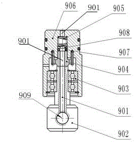
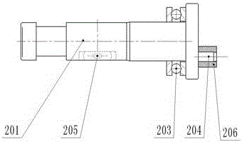
[0021] Embodiment 1, see attached Figure 1-4 : A variable-angle fan, comprising a base body, 6 fan blade shafts 201 that can rotate within 30° clockwise and counterclockwise relative to the base body, and 1 fan blade fixedly connected to each fan blade shaft 201, the fan blade A fan blade installation groove 205 is opened in the middle of the shaft 201 for fixing the fan blade. The positioning pin 204 is arranged eccentrically on the inner end surface of the fan blade shaft 201; the base body includes the cylinder body 5, the connection plate 17 and the fan seat body 3 between the cylinder body 5 and the connection plate 17, and the three are fixedly connected Together and surround the cavity 53; the cylinder 5 has an inner annular groove and an outer central hole, and an oil inlet part 900 that can be fixed relative to the cylinder 5 is arranged in cooperation with the outer central hole; an annular ring is arranged in cooperation with the inner annular groove. Piston 6, an...

Embodiment 2

[0031] Example 2, see Figure 1-3 , 5 Others are the same as embodiment 1, the difference is that because the oil pressure of the hydraulic source exceeds the working range of the variable angle hydraulic fan oil pressure, a pressure reducing valve is arranged in front of the two-position three-way solenoid valve. In order to realize automatic control, the manual self-resetting switch can also be removed, and its control line is connected with the automobile ECU, so as to realize automatic control.


PUM


Abstract

The patent of the present invention discloses a variable angle fan, which realizes the parallel and non-parallel control of the blade angle by controlling the oil pressure of the solenoid valve, and realizes the problem of changing the airflow size at low cost, and then adjusts the positive and negative angles of the non-parallel angle. The effect of changing the air flow direction is realized, and the purpose of automatically cleaning the water tank and improving the heat dissipation efficiency is achieved. Compared with the prior art, the invention has the advantages of simple structure and low cost, and can meet the engineering application.

Description

technical field [0001] The patent of the invention relates to the technical field of automobile heat dissipation, and specifically relates to a variable-angle fan, which controls the oil pressure through a solenoid valve to realize the parallel and non-parallel angle between the fan blade and the rotating surface. Background technique [0002] The heat dissipation of the existing engine cooling system is mainly to drive the cooling fan directly or indirectly through the engine crankshaft to take away heat. The blade angle of the fan is a certain value, which makes the exhaust air volume of the fan not well matched with the heat dissipation of the engine. Under low-temperature and light-load conditions, the exhaust air volume of the fan is too large, resulting in high power consumption; the cooling fan blades cannot operate at the optimal operating temperature, resulting in reduced fuel economy and increased energy consumption. The current domestic patent: an electromagnetic...

Claims


Application Information

Patent Timeline
Patent Type & Authority Applications(China)
IPC IPC(8): F01P7/06
CPCF01P7/06F01P2050/22
Inventor 刘中银王艳立刘学文
Owner LONGKOU ZHONGYU THERMAL MANAGEMENT SYST SCIAND TECH
Why Eureka
Try Eureka