Resistance strain gauge bonding and calibration method capable of measuring contact pressure of disc friction pair

A technology of resistance strain gauge and contact pressure, applied in the direction of measuring force, measuring device, force/torque/power measuring instrument calibration/test, etc., can solve problems such as error, resistance strain gauge falling off measurement, etc., and achieve easy operation and testing The effect of low cost and simple calibration method

Inactive Publication Date: 2016-09-28
LIAONING INST OF SCI & TECH +1
View PDF4 Cites 5 Cited by
  • Summary
  • Abstract
  • Description
  • Claims
  • Application Information

AI Technical Summary

Problems solved by technology

[0004] The technical problem to be solved by the present invention is: in order to solve the measurement error caused by the loss of the resistance strain gauge and the radial sticking error under the condition of high speed and heavy load in the prior art, a method for measuring the contact of the disc friction pair is provided. Pressure resistance strain gauge pasting and calibration method, this method effectively solves the above problems, and lays the foundation for the subsequent on-site pressure measurement of the pair

Method used


Image

  • Resistance strain gauge bonding and calibration method capable of measuring contact pressure of disc friction pair
  • Resistance strain gauge bonding and calibration method capable of measuring contact pressure of disc friction pair
  • Resistance strain gauge bonding and calibration method capable of measuring contact pressure of disc friction pair

Examples


Embodiment Construction

[0024] In order to clearly illustrate the technical features of the solution, the solution will be described below through a specific implementation mode and in conjunction with the accompanying drawings.

[0025] Both theoretical research and experimental process have found that the stress distribution of Fe-based powder metallurgy friction pairs is not uniform during the bonding process, which is due to the characteristics of the pressurized structure and the characteristics of the contact surface. In order to realize the high-precision test of the contact stress of the friction pair, in view of the high-speed and heavy-load working environment of the pair, the strain gauge type is strengthened and the moisture-proof work is carried out. The calibration method is simpler, faster and easier to operate.

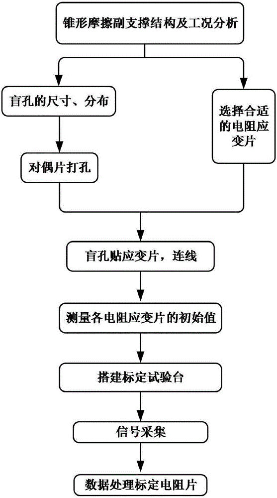
[0026] Such as figure 1 As shown, the present invention pastes the resistance strain gauge at the bottom of the blind hole and its calibration method. The specific operation ...


PUM


Abstract

The invention discloses a method for pasting and calibrating resistance strain gauges for measuring the contact pressure of disc friction pairs. Firstly, the characteristics of the external support structure of the friction pairs are analyzed to determine the size and layout of blind holes and the range of resistance strain gauges. According to the position of the blind hole, connect the patch and measure the initial resistance value of the resistance strain gauge at each measuring point, judge whether the pasted strain gauge is normal, then build a calibration test bench and carry out signal collection, and finally carry out the test through the data of each measuring point The fitting process obtains the calibration value of the measuring point resistance. The invention can realize the measurement of the strain of the paired sheet under the known loading pressure. Due to the welt angle and accidental factors, the strain gauge values ​​at each measuring point are different. If the direct pressure loading experiment will cause a large number of The calibration experiment provides a basis for correcting the dynamic and static pressure distribution measurement data of the friction plate. The calibration method of the present invention is simple, fast and easy to operate.

Description

technical field [0001] The invention belongs to the technical field of stress and strain measurement on contact surfaces of friction pairs of brakes in the transmission field of crawler vehicles, and in particular relates to a bonding and calibration method of resistance strain gauges for measuring the contact pressure of disc friction pairs. Background technique [0002] High energy density friction transmission system is the key to high performance transmission. Its distinctive features are high power and high speed. The friction pair is widely used in the transmission field of tracked vehicles due to its excellent wear resistance and high heat capacity. Cu-based and Fe-based powder metallurgy friction pairs, including brakes and clutches, work in a multi-stress compound environment. As the three-parameter boundary-pressure, speed, and temperature are the main factors affecting the friction characteristics of the friction pair, and they are also the key factors in the desig...

Claims


Application Information

Patent Timeline
Patent Type & Authority Applications(China)
IPC IPC(8): G01L1/22G01L25/00
CPCG01L1/22G01L25/00
Inventor 孙国军姜连志陈锐郭超吴向宇王延忠
Owner LIAONING INST OF SCI & TECH
Why Eureka
Try Eureka